Home
About
Acknowledgments
Documentation
Gallery
(current)
Contact
Gallery
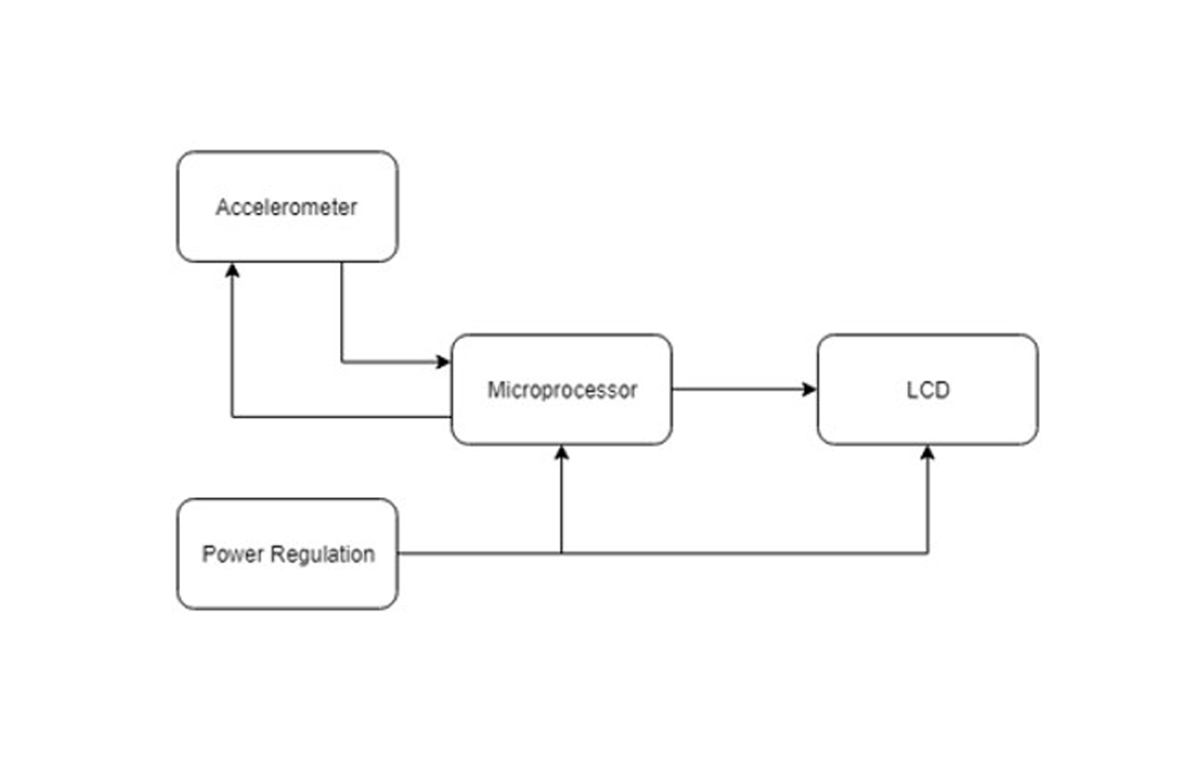
Functional Decomposition I
First functional decompostion that we designned. It is very general, with the modules not begin too defined.
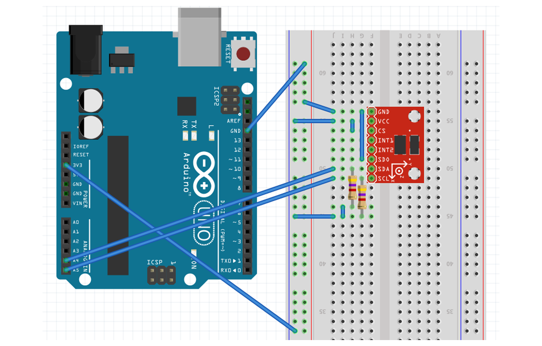
Fritzing Image
This shows the diagram of how the arduino interacts with the accelerometer and what GPIO pins are used.
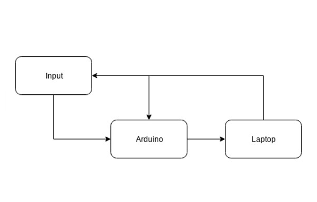
Functional Decomposition II
Here the modules are more defined, and the whole decomposition is simplified.
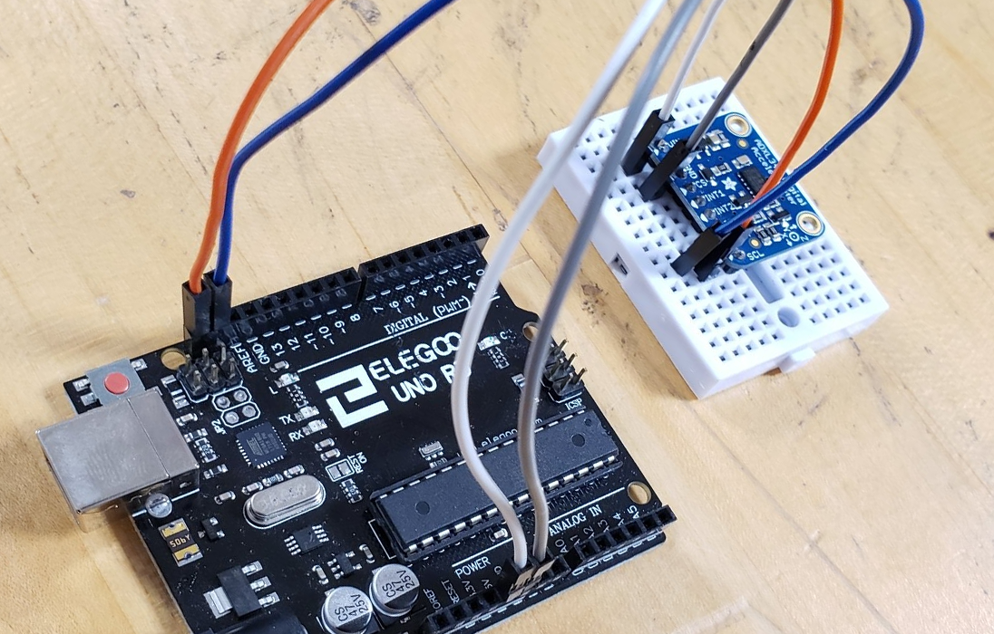
Device with breadboard
This is a picture that shows how the device looks when everything is wired.
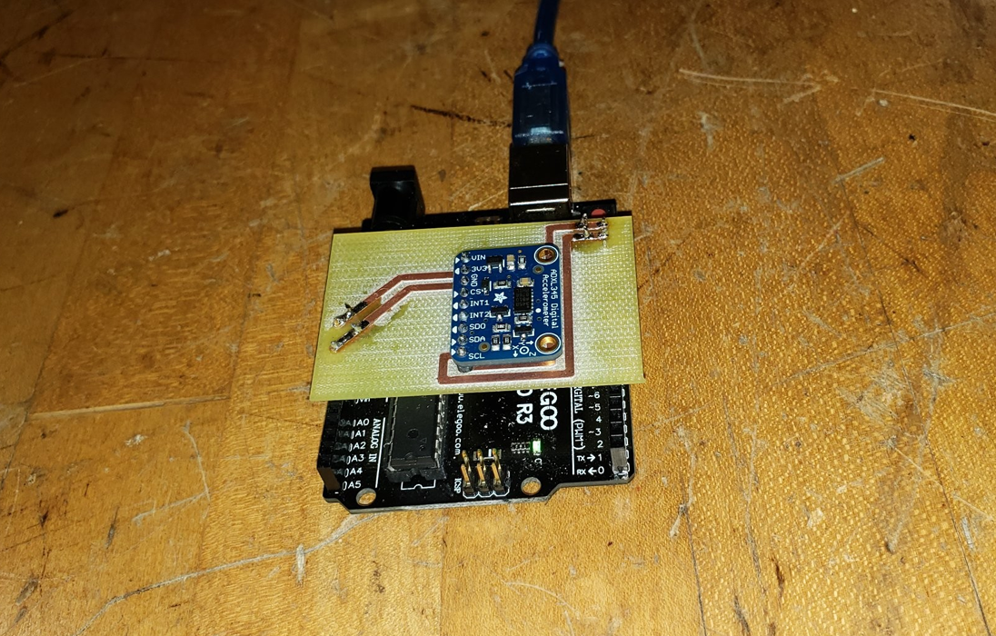
Device with printed circuit
This is a picture that shows how the device looks when everything is wired and soldered to a printed cirquit board.
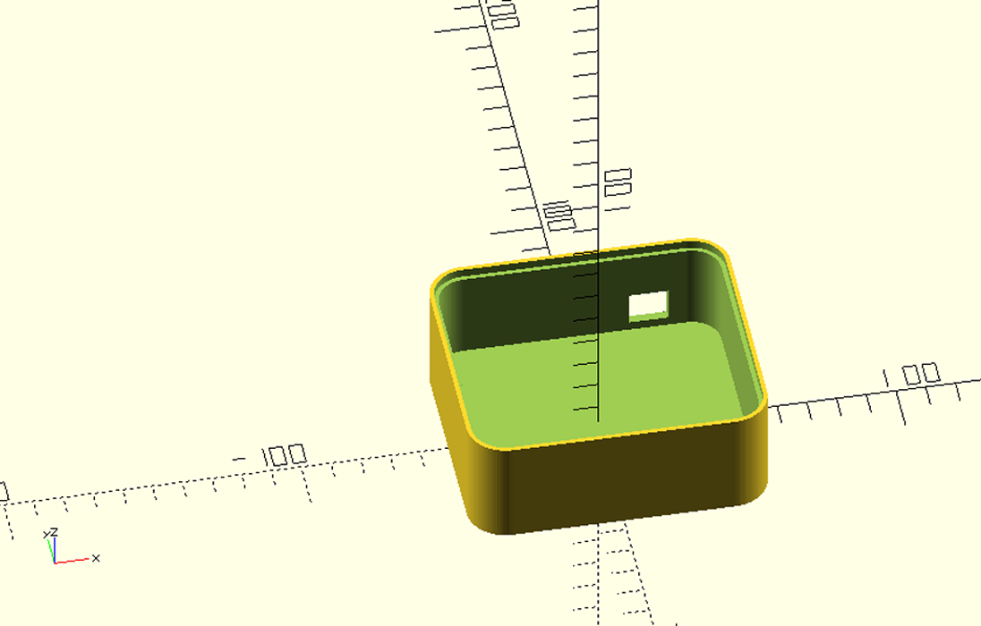
Model for casing
This shows the model for the case for the device, this model will be 3D printed and the device will be held inside.
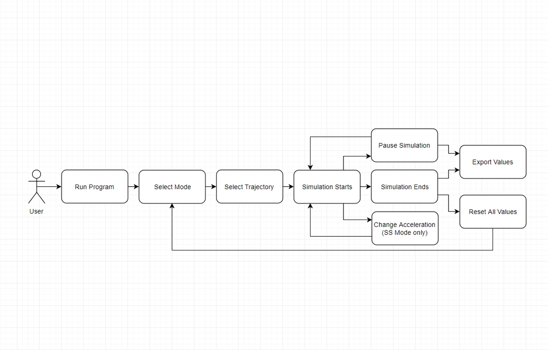
Usage Flowchart
This shows how the user interacts with he simulation software, and what steps the user needs to take to use the program correctly.
Screenshot of Liftoff Mode
This shows how liftoff mode looks in the simulation.
Screenshot of Orbit Mode
This shows how orbit mode looks in the simulation.