Proof-of-Concept Device:

The team decided to develop a hardware prototype to verify our simulation results. The device measures acceleration to determine how fast an object is moving, and calculates time dilation from there.

Initial Design


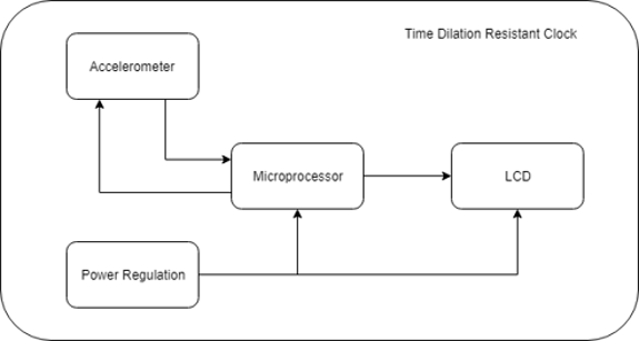
The team identified a few main needs for the project to function – measurement accuracy, easy integration, and a simple and modular design. To this end, the team chose to split the project into three main blocks: input, processing, and display. The input block was selected to be an accelerometer. The processing was to be done with a microprocessor with sufficient clock speed. Lastly, the adjusted time and proper time were to be displayed on an LCD. Power was supplied through a DC source (battery) and distributed to the microprocessor and display.

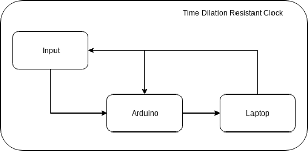
Functional Decomposition v1


Functional Decomposition v2


Revision 1


After several design reviews, input from advisors, and working with the actual system, the device was partially redesigned. It would still use a microprocessor to sample from an accelerometer, but the input will be scaled to simulate conditions not easily testable on Earth (velocities approaching the speed of light). Initially, the input was going to be handled with a Kalman filter to reduce inaccuracy. Problems with implementation on the chosen microcontroller (C3000 Delfino MCU) and control data for the filter led to the MCU being switched to an Arduino. It is an assumption by the team that the data is accurate enough to generate approximate results. The data will then be sent to the console of the Arduino, where it can be easily stored and reviewed for analysis. Power is handled by the laptop, with conditioning occurring on the Arduino board.

Revision 2


This image shows an image generated by the program Fritzing. It shows the wiring for the I2C configuration of the ADXL345 accelerometer. Notice that the CS (Chip Select) pin is wired to VCC. If wired to ground, the chip will interpret this as SPI mode, and none of the read data (if it is readable at all) is valid. Additionally, notice that the SDA and SCL (Serial Data and Serial Clock, respectively) are pulled high. This is important to make sure that the data being sent over these lines is coherent. This image was developed to aid in understanding the wiring and for future work on the project.

Fritzing Diagram


Actual Device


Current Design


The second revision device is shown here. The new accelerometer (ADXL345) is operating in I2C mode, sending data to the Arduino. An Arduino was substituted to be able to rapidly prototype with the new board. There was a premade library for this device, minimizing the need for new code on a tight schedule. It currently reads the velocity to a degree of accuracy of 0.01 meters per second. It does this by taking an average of the acceleration, multiplying by the time interval, and subtracting a constant factor. The constant factor (bias velocity) was determined by taking a sample of acceleration over a time period of one hour and finding the average “resting” velocity. It then multiplies the calculated velocity by a scaling number to produce a visible dilation. It outputs this to the console of the computer, and in future revisions, an LCD.