Team 302: Frequency Multiplier
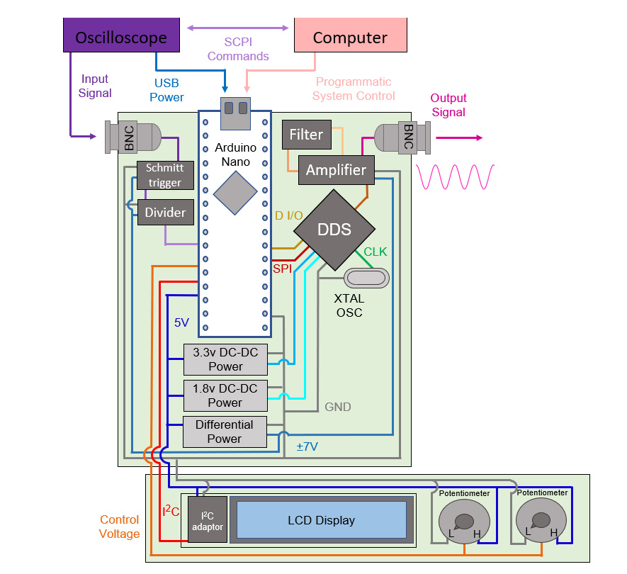
Oscilloscope

While the DSOX1204G was used for this project as a base, any Oscilloscope with a USB outlet will be able to work with the Multiplier independently. In the case that you do not have a scope with a USB outlet, you can also use a computer to power the multiplier, as well as utilize the computer controls.
The DSOX1204G was used to form some of the requirements for the Multiplier, specifically the input and output range. This scope can read in signals up to 200 MHz; however, the built-in function generator can only create signals up to 20 MHz. Bridging this gap is the main goal of the project, however as a result of our design we can reach the full range up to 200 MHz.
Back to Image
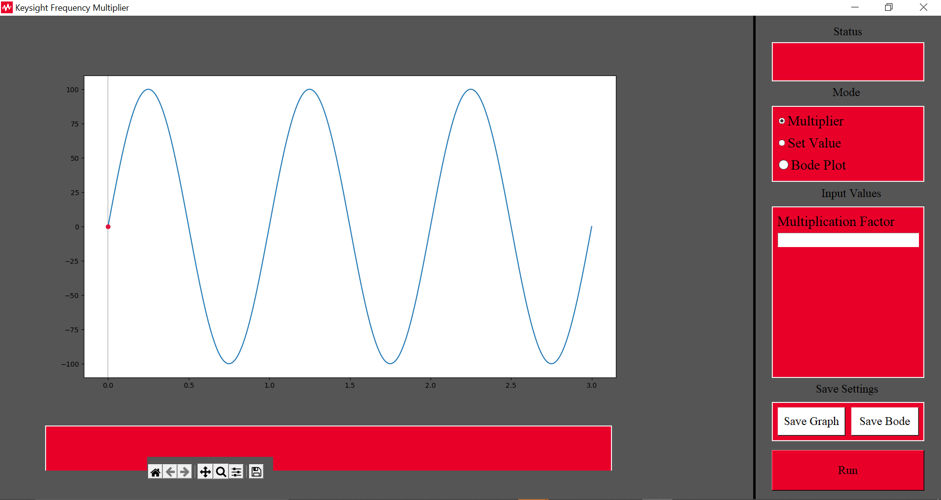
Computer
Our computer controls needed to meet 2 major requirements. The first being for a 100 Hz step size between signals, and the second being the more in depth bode plotting system. The goal of this system is to allow for the rapid scanning through a range of signals and is a powerful tool for electrical engineering.
Outside of these two requirements, the computer controls should allow for easy access to not only the multiplier’s settings, but also the data received from the scope. This allows not just easy visualization on the computer, but the ability to save the data locally to use in other programs. All of this is accomplished using Python as our code base, including open-source libraries.
Back to Image
Schmitt Trigger
Due to our Microcontroller’s clock speed, we can only read signals up to 6.5MHz naturally. To overcome this challenge, we use a flip flop divider on the signal. The chip we decided on however runs into problems with sine waves, and so the CD4093BPWR Schmitt Trigger is used to convert our sine wave input into a square wave.
Back to Image
Divider
Due to our Microcontroller’s clock speed, we can only read signals up to 6.5MHz naturally. To overcome this challenge, we use a flip flop divider on the signal. The SN74LS74AN is an affordable 4x divider that can decrease the frequency at our high end of 20 MHz to a readable 5 MHz.
Back to Image
Arduino Nano
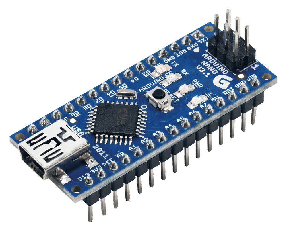
To connect all our components, we require some centralized component to control the Multiplier. For that we went with a microcontroller, specifically the Arduino Nano, as they are, affordable, accessible, and easy to interface with. The Nano specifically can be purchased for $5 from amazon, is open source, and can interface with the Python used for computer controls.
Back to Image
Power Supplies
Outside of the natural 5V power we have from the Arduino, we also require 1.8V and 3.3V for our DDS chip, and differential 7V for our amplifier, divider, and Schmitt trigger. To achieve these, we use the components XCL220b183FR-G, PDSE1-S5-S3-S, and PDM2-S5-D7-D chips for 1.8V, 3.3V and differential 7V respectively, as they are all reliable and affordable chips.
Back to Image

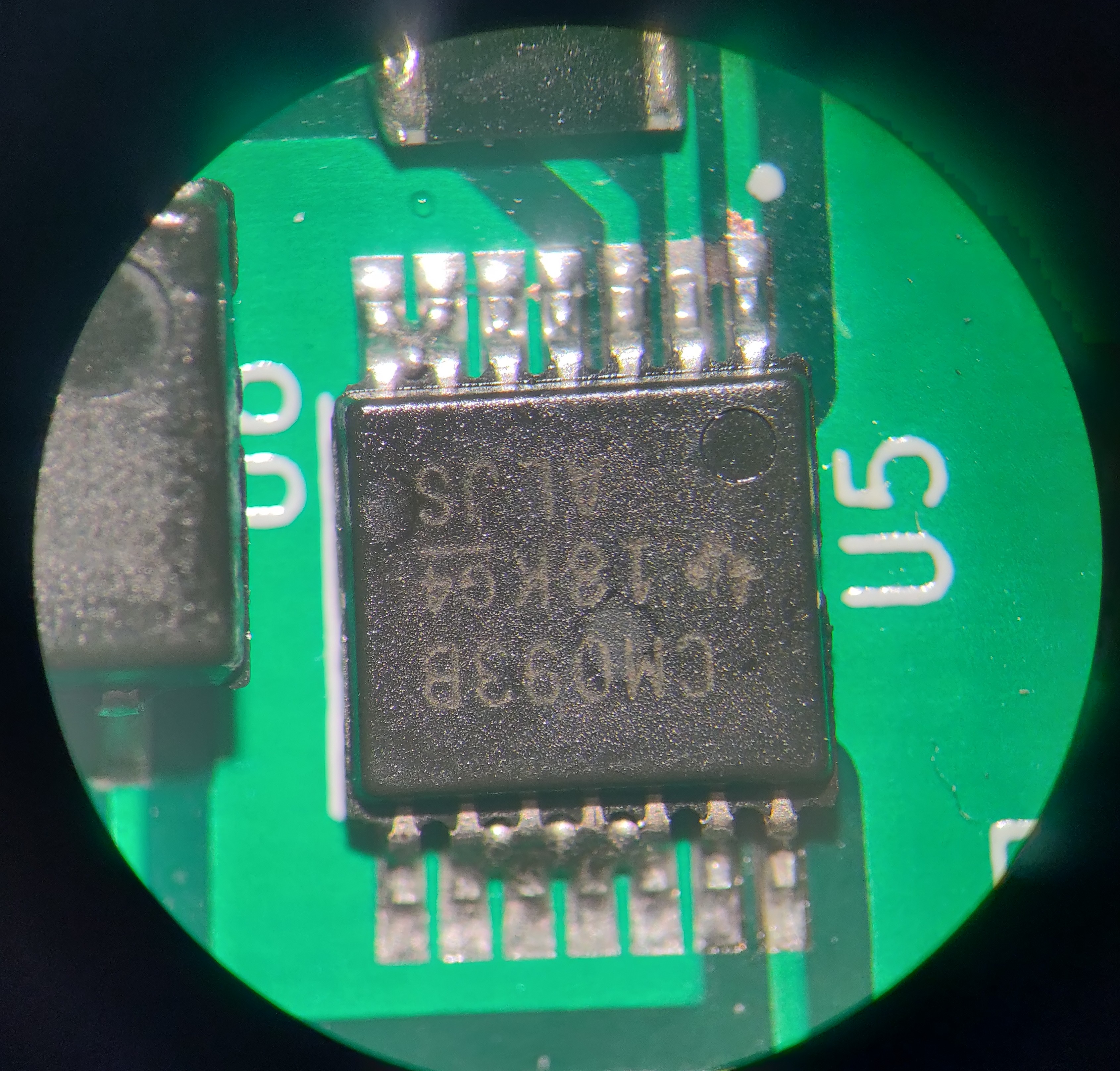
DDS
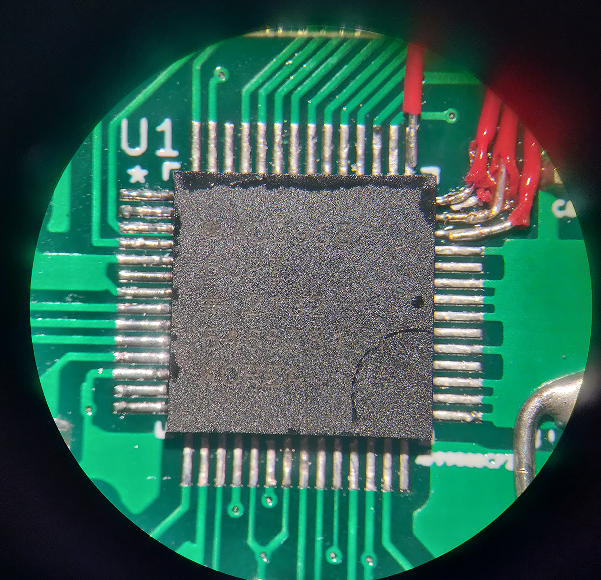
Early on the choice of multiplication lead to two options, physical multiplication through a Phase Lock Loop (PLL) system, and digital multiplication, using a Direct Digital Synthesis (DDS) chip. There were many considerations, such as availability, cost, ease of implementation, and integration. Eventually the DDS option became the standout choice with its biggest detriment, availability, being solved with our sponsor acquiring out of stock chips that perfectly matched our specs, as well as an evaluation board which accelerated our progress greatly.
The DDS chip in question is the AD9958. This chip can synthesize a signal up to 200 MHz in frequency with a step size of less than a single Hz. It interfaces well with our microcontroller using SPI and Digital I/O commands and can run utilizing a 25 MHz clock signal generated with a stand-alone crystal.
Back to Image
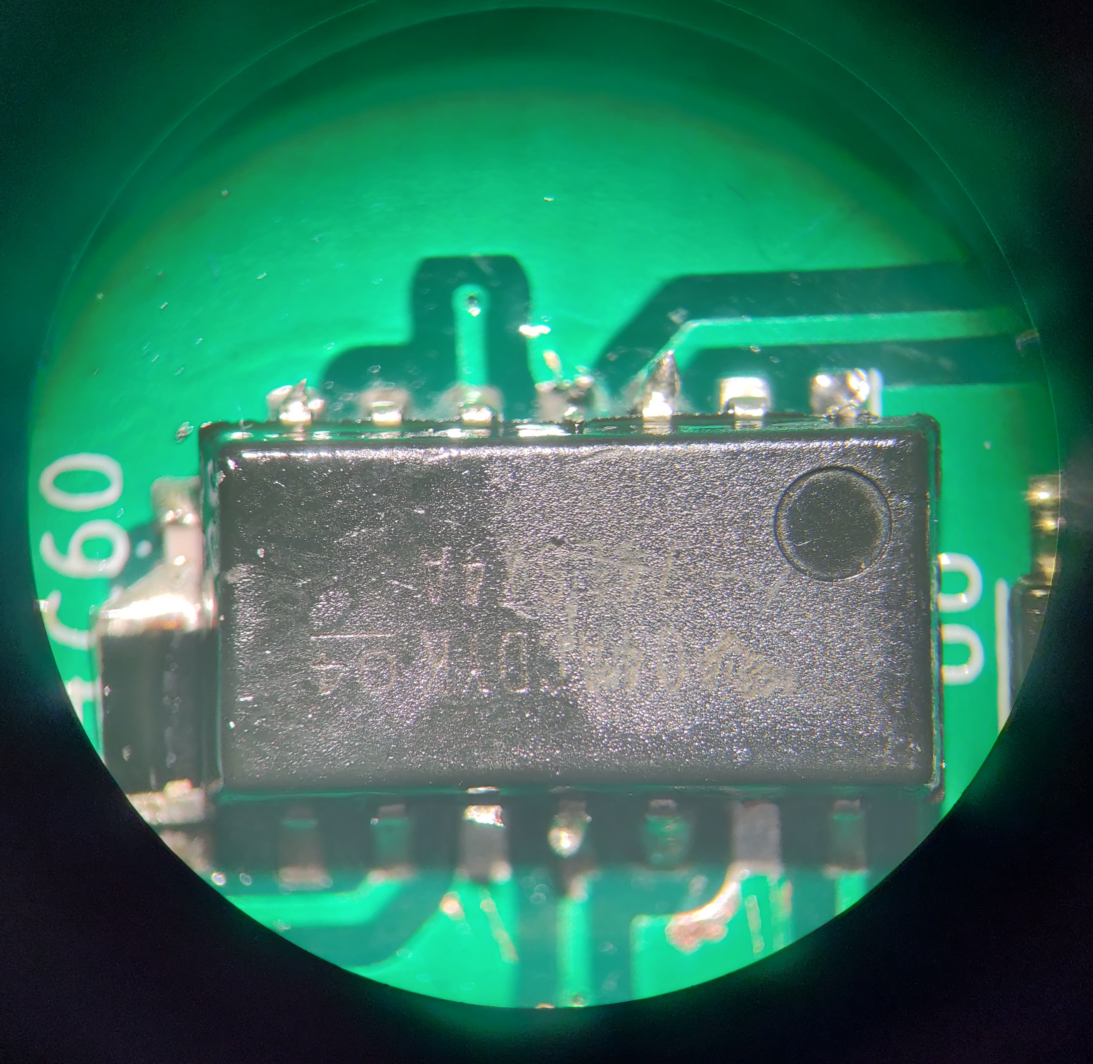
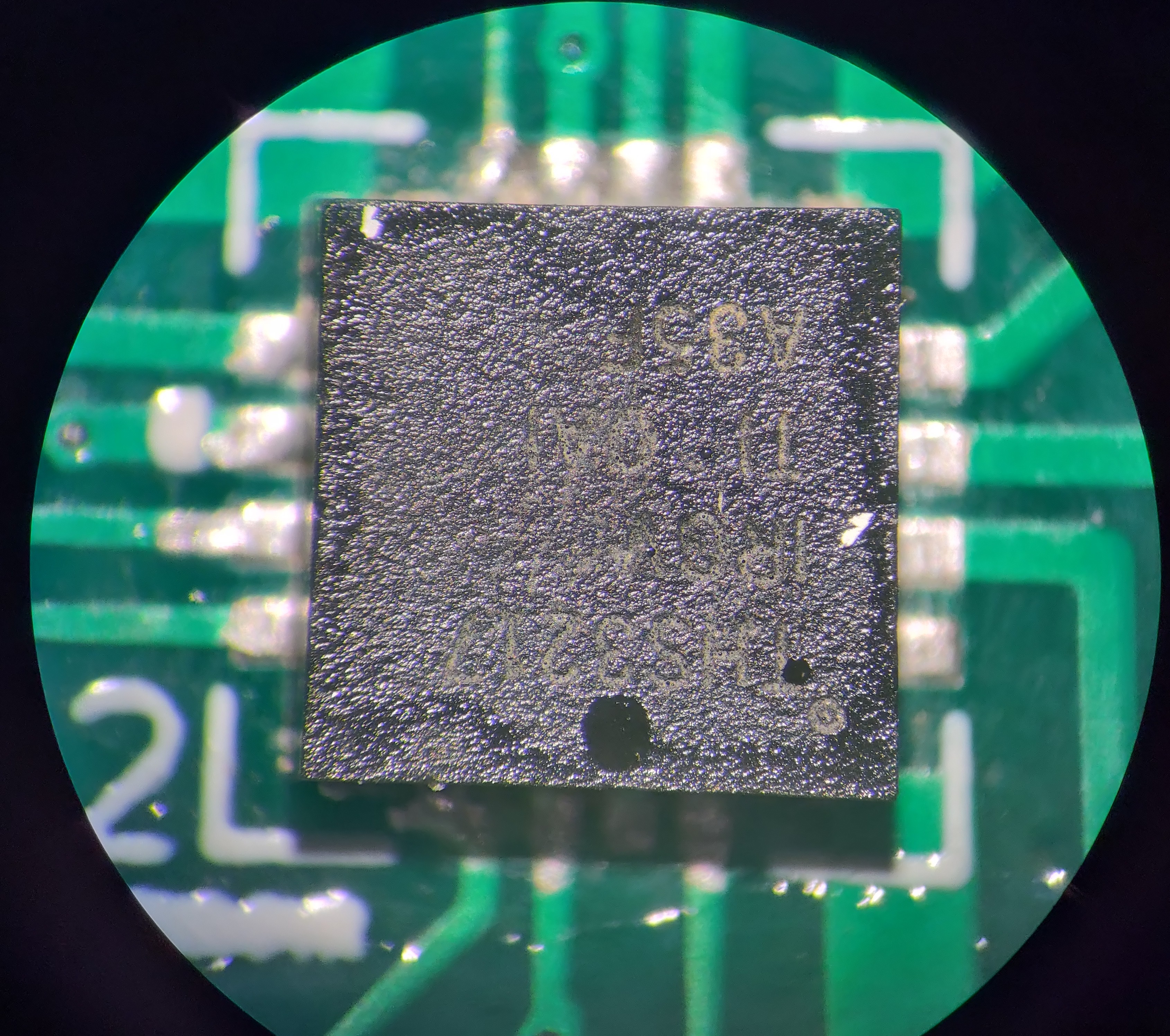
Amplifier
One problem we ran into early on with the evaluation board was problems reaching the lower ranges of frequencies. Bellow 30 kHz, strange distortion would be observed that resulted in an unusable frequency. Inspecting the evaluation board showed that the cause of this was the transformer used at the output stage, and thus a new component was needed.
Under recommendation of our Sponsor, we eventually chose the THS3217, a very powerful Operational Amplifier. This not only fixes our problem at the lower end but helped meet another requirement with our output voltage being over one volt peak to peak.
Back to Image
Filter
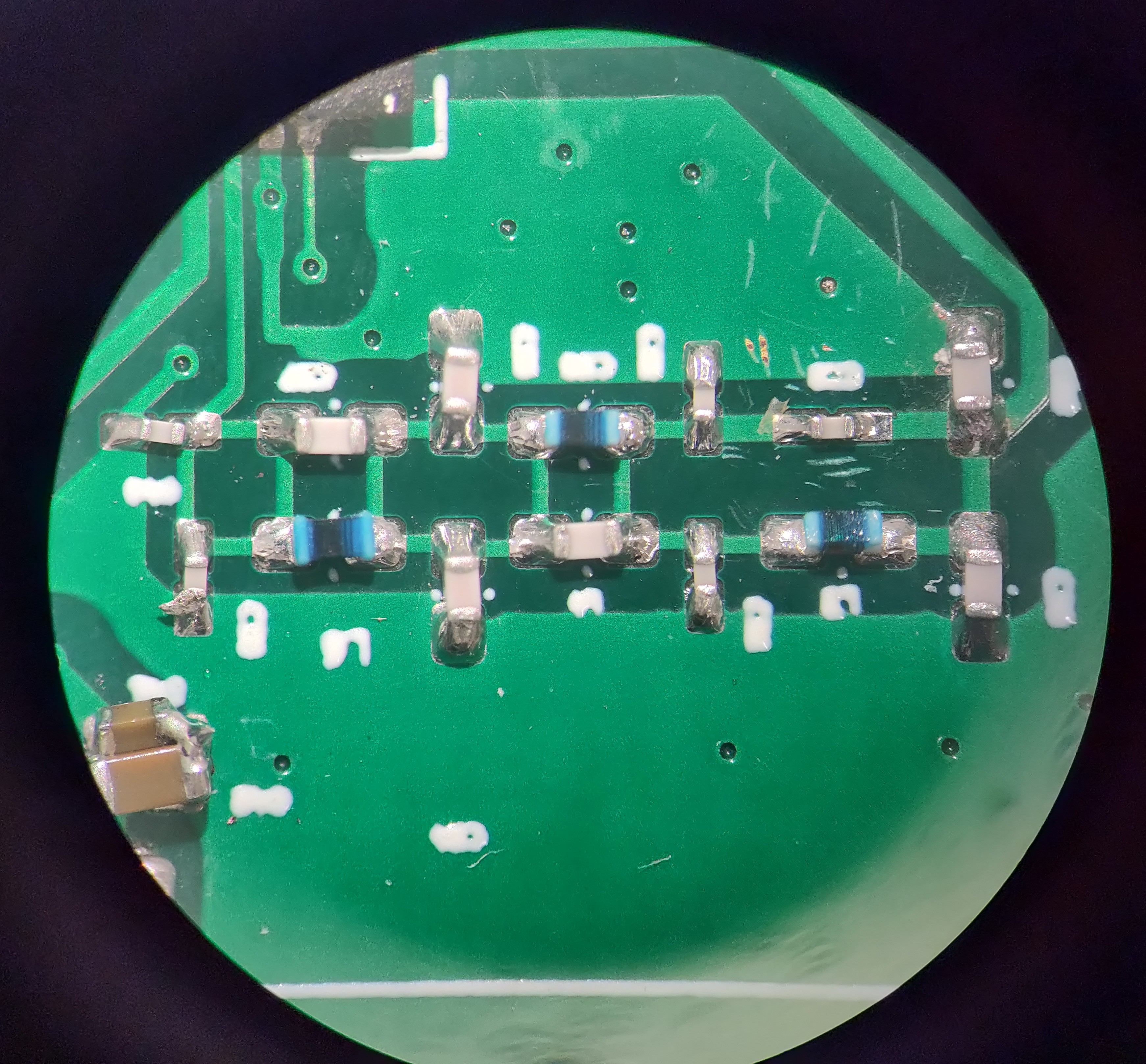
The Filter we are using is based off the evaluation board’s filter, being a very complex low pass filter. This allows for all frequencies bellow 200 MHz to pass through, however has a sharp cut off for frequencies above it, causing faster frequencies, such as the 500 MHz clock signal the DDS uses from the 25 MHz crystal, from leaking into our final signal and causing noise.
Back to Image
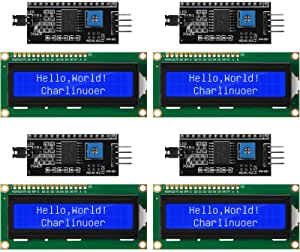
LCD Display
The LCD display we chose is a simple 16x2 LCD that allows us to express enough information to show the current setting and value of our output for the user should they not be directly measuring it. Using the I2C module for our specific LCD, we can also cut down on the connections we need to make to the LCD, as well as simplify the code needed to control it.
Back to Image
Potentiometers
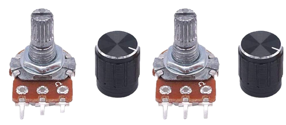
For the On Unit Controls, two simple Potentiometers are used. The first is used to determine the mode, between Off, Multiply, three ranges of set values, and finally computer controls, while the second used for selecting the wanted value. 100k is used as a way to limit the power used by these components.