Team 309: Piezoelectric Accelerometer

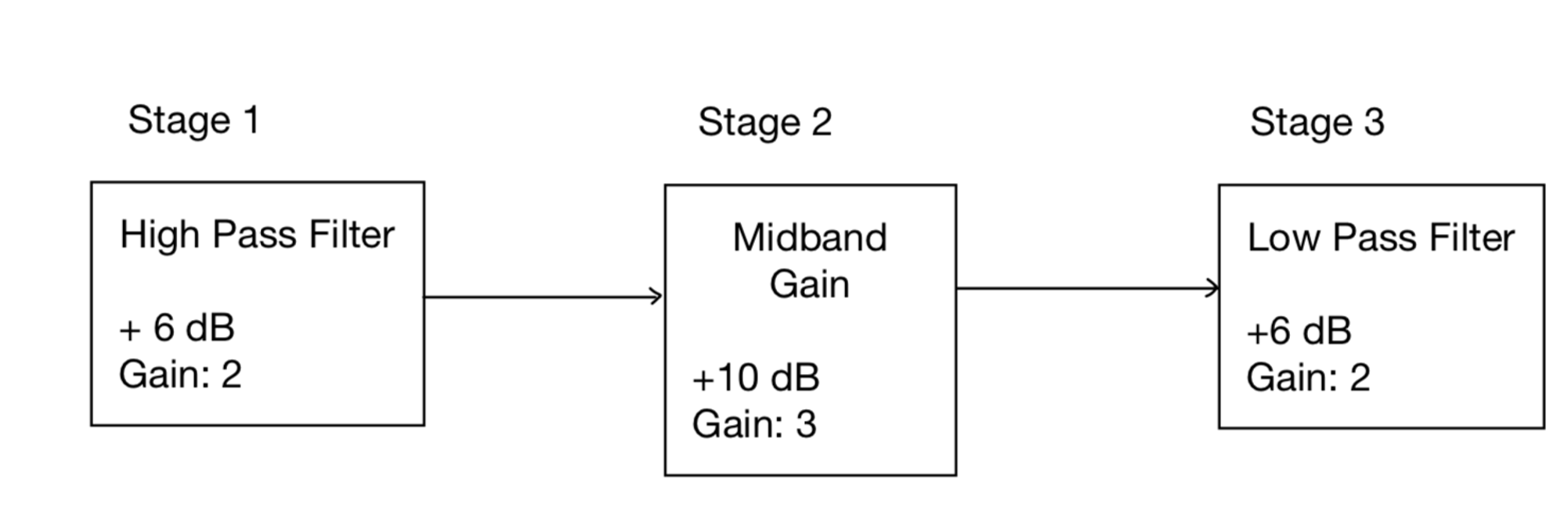
Signal Conditioning Stages
Since the sensors produce such a small amount of charge, signal conditioning circuitry is required to successfully extract the acceleration information without any charge being dissipated. This requires amplification stages with large input impedance to prevent the produced charge from leaking off through the input impedance of the amplifier that is in parallel with the sensing element.
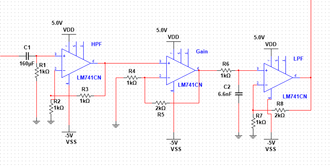
Signal Conditioning Circuit
The electronics of the IEPE sensor convert the high impedance signal of the piezoelectric material into a voltage signal with a low impedance of typically 100 Ω. A low impedance signal is advantageous because it can be transmitted across long cable lengths without a loss of signal quality. In addition, special low noise cables, which are otherwise required for use with piezoelectric sensors, are no longer necessary. The sensor circuit is supplied with constant current. A distinguishing feature of the IEPE principle is that the power supply and the sensor signal are transmitted via one shielded wire. Most IEPE sensors work at a constant current between 2 and 20 mA. A common value is 4 mA. The higher the constant current the longer the possible cable length. Supplying the IEPE sensor with constant current, results in a positive bias voltage, typically between 8 and 12 volts, at the output. The actual measuring signal of the sensor is added to this bias voltage. The supply or compliance voltage of the constant current source should be 24 to 30 V which is about two times the bias voltage. This ensures maximum amplitudes in positive and negative direction. A typical IEPE sensor supply with 4 mA constant current, and 25 V compliance voltage has a power consumption of 100 mW.