Cryogenic Particle Condenser: The Final Product
The CPC system consists of 23 parts. Very few of which are moving parts, reducing the risk of mechanical and cyclical failure. This page shows some of the individual parts, with a short description of what they are. Finally, the product of over 8 months of hard work, the cryotrap in its entirety shall be unveiled.
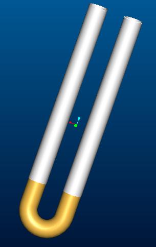
This is the U-pipe which is inserted into the nitrogen vessel, and contains the copper mesh - indicated in copper. This is the location where the particles are trapped.
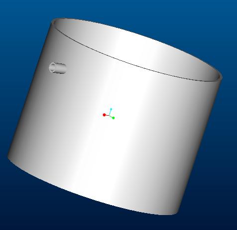
This is the general shape of the canisters. The vacuum jacket and nitrogen vessel have this shape. The small protrusion here represents the vacuum pump seal for the vacuum jacket.
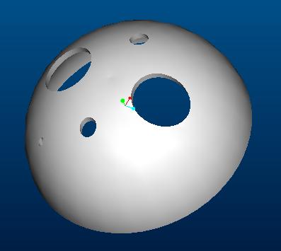
This is the end caps for the canisters. The holes in it show where all the external equipment will be placed. The two large holes represent where the helium in-out lines will be, the two smaller holes represent the nitrogen fill line and vent, and the offset hole is where the thermocouple for the monitoring system is placed.
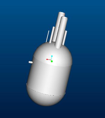
This is the assembled cryotrap. Here you can see the protrusions of the nitrogen and helium lines, along with the thermocouple line. Contained within is the nitrogen vessel which is a few inches off the side of the vacuum jacket. within that is the U-pipe and copper mesh.
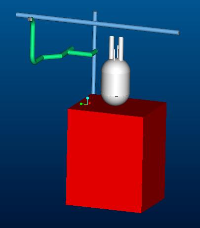
Here is the approximate assembly of the cryotrap in relation to the compressor room at the NHMFL. For a detailed picture see the pictures page.