Senior Design: Becoming Engineers
The senior design course is a two semester sequence of classes designed to train engineers how to utilize their technical knowledge and apply it to real world projects.
At the beginning of the fall semester of our senior year, the teacher, Dr. Cesar Luongo, introduced over twenty projects to the class. Then, based on academic standing and past performance as evaluated by the faculty of the ME department, the students were divided into four groups. Each project would end up having an individual from each group of students. This was to assure diversity in the group.
The students were randomly drawn from an envelope, and were then allowed to choose which project they would like to work on.
Our group chose project number eighteen.
Project
Project number 18 was in fact a choice of projects. Our customer, John Kynoch of the National High Magnetic Field Laboratory, told us we had a choice of two projects that he was working on at the time.
The first project was an HVAC problem involving a wing of the NHMFL building. We were told that the current air conditioning system had a problem, it wasn't providing enough cooling to the wing. The system had been designed for a certain amount of heat load, and it appeared that the heat load was exactly as had been expected. Our job was to determine the reason for the problem. This would consist of determining how much heat was being emitted by all the equipment, personnel, and from the outside, then figuring how much heat the AC system was taking out. Finally it was our task to determine where the failure had occurred, if it was the AC system or some unexpected variable, then determine how best to fix it.
The second project we were given was for the 40T Hybrid Magnet. This project involved the construction of a device that would remove water and oil from a helium flow. Helium for the hybrid magnet is cooled down to 4°K to make it a superfluid. An evaporator system is used to cool the helium down. A vacuum pump is used to evaporate the helium. The seals on the vacuum pump have become swollen with a lot of use, causing small leaks into the helium flow. These leaks causes water and oil to enter the helium stream, thereby contaminating it. The liquefier, which changes the evaporated helium to liquid for insertion back into the evaporator, becomes clogged when the contaminants freeze within it. The particle removal system would remove this problem.
After some debate, it was decided that the second project should be chosen, as it was the most challenging in all aspects.
John Kynoch introduced us to these types of devices, referring to them as cryotraps. He also laid out a detailed description of the project as he saw it, called the scope.
Scope
The scope of the project is to build a cryotrap to catch the contaminants (water, nitrogen and oil) that enter the system of the Hybrid Magnet at NHMFL (National High Magnet Field Laboratory). The function of a cryotrap is to freeze and capture the elements that are not desired in the system, while allowing the desired element to pass through without adverse changes to the system. The Hybrid Magnet uses liquid helium to cool down the magnet. Since helium does not become a liquid until it reaches 4°K a large evaporator system is used to liquefy the system. Some helium is evaporated off a larger amount of helium using vacuum pumps, causing it to cool down to the temperatures needed. The helium which is evaporated off is then pumped through a vacuum pump into a condenser, which then pushes the helium to a liquefier, which liquefies the remaining helium. This helium is then returned to the magnet.
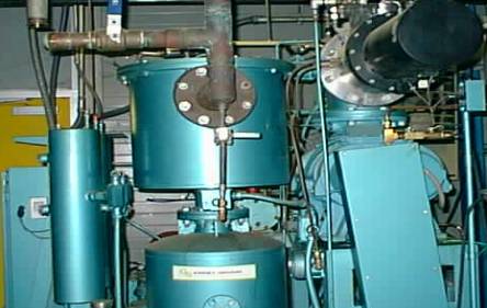
Figure 1. Vacuum Pump
The problem with the existing cooling system for the hybrid magnet at the National High Magnetic Field Laboratory (NHMFL) is contamination. Foreign particles, mainly oil and water, are being introduced to the helium flow. When helium reaches a temperature of below 4° Kelvin, its properties change and it becomes what is known as a superfluid. Also, its thermal conductivity is enormously greater than a non-superfluid, therefore conduction occurs almost instantaneously between two points. Such a high thermal conductivity helps greatly in cooling down the hybrid magnet. However, the liquid helium can only become a superfluid if it is a pure substance. Therefore, there is a need to rid the current system of all contamination. The current setup utilizes an evaporator, vacuum pump, condenser, and liquefier for the circulation of liquid helium. After the helium circulates around the magnet and absorbs its heat, it is sent to the evaporator. This is because the heat from the magnet causes the liquid helium to begin to turn into gaseous helium. The evaporator then liquefies most of the helium, but a portion of the helium is sucked through the vacuum pumps. The vacuum pump then pumps this helium through to the liquefier which uses pressure and temperature to change the remainder of the helium into a liquid. Due to the poor condition of the seals used in the vacuum pump (Figure 1), water and oil are introduced into the flow. However, the compressor is equipped with a device that filters out oil from the system. Thus, the only contaminant that is of concern is water. This water is mixed in with the liquid helium flow and when it reaches the liquefier, it freezes and causes the liquefier to become clogged. At first, it might seem like the logical step would be to simply replace the faulty seals. This would however take a good deal of time and would have to done on a routine basis. In order to replace the seals, the entire system would have to be shut down and them brought back online, which costs thousands of dollars in opportunity losses. Therefore, a device is required to filter out the water particles while allowing the system to run continually.
The first semester of the senior design course is devoted to teaching the students the design process and techniques. Here the iterative process of design is taught, which is then to be implemented by the students into their projects. The design portion, was meant to be technical in nature. The students were to use their scholastic knowledge to develop a system on paper, the second semester would be used to build their projects.
Coming into the design portion of the semester, our group had only a vague idea of what a cryotrap was, let alone any idea how to build it. The information we had told us three things we had to do. The first, determine a way to cool the helium flow down so that the water would freeze. Second, a device or method to trap these particles out of the helium flow. Finally, some way to remove the contaminants would be needed.
It didn't take us long to determine the reason why the device is called a cryotrap. It become obvious that due to the low partial pressure of the contaminants that a very low temperature fluid, a cryogenic fluid, would be needed to cool the flow down. Our two choices were helium or nitrogen. At first it seemed to the team a good idea to recirculate some of the liquid helium into the cryotrap. Its low temperature would assure that practically all the contaminants would freeze out. It was soon learned that insulation for a liquid helium line was a few hundred dollars per foot, making it cost prohibitive. Liquid nitrogen became our choice cryogenic.
With a method of cooling the helium flow done, it was time to move onto the method of trapping the water. After several designs were drawn, the group discussed which one had the most potential. We believed that a straight pipe, with a large diameter was the best system. The large diameter would not only cause the flow velocity to slow down but also to provide a large surface area for the water to collect on.
After some research, it was discovered that nitrogen has the remarkable property of expanding to several times its initial volume when boiling. This meant that the liquid nitrogen container would become an explosive pressure vessel if left unchecked. A method of insulating the liquid nitrogen, along with a way to regulate the internal pressure had to be determined.
After speaking with Kurt Cantrell, we learned that a vacuum jacket is the best method by which to insulate the liquid nitrogen. A vacuum jacket works by removing heat transfer by convection and conduction. Radiation would be very little because the change in temperature between the two surfaces would be very small comparatively. We also learned that a vacuum jacket would fail if a vacuum was placed on a long tube. This meant that our long pipe design would not work. Back to the drawing board!
We decided, after some computation that a cylindrical vessel would be the best shape for the cryotrap. A U-pipe would be placed inside the liquid nitrogen vessel for the helium flow. The cylindrical vessel was similar in length with both the diameter and height dimensions. To increase the amount of contaminant trapping, we decided to add a specially designed copper mesh that would be inserted into the U-pipe.
The venting system for the liquid nitrogen system was the next step to tackle. At first a pressure relief valve was included in the design, but after discussion it was deemed that if a failure of the valve were to occur, the whole system might actually explode. This would not be acceptable. After some thought, we came to the conclusion that a long copper tube that allowed the nitrogen to boil off to atmosphere would be best. By adding bends in the piping and regular insulation to the outside of the pipes, the thermal transfer of heat to the nitrogen from the atmosphere would be decreased.
The nitrogen monitoring system has a dual purpose: monitor the level of the nitrogen in the vessel, and fill the tank when necessary. The system chosen is made by American Magnetics Company. The system uses a thermocouple to measure the level of the nitrogen based on temperature, when the level goes below a certain point, the monitor activates a solenoid valve which allows the nitrogen to pour into the vessel.
This concluded the design portion of the project. With these parts we were able to create an assembly procedure that would then be used by the NHMFL to build our cryotrap. This is the final product.