Assembling
Propeller and Motor
Connecting
Motor, Power Supply, and Ammeter
Figure
1. Wire setup of Apparatus
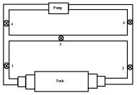
Figure
2 Piping and Valve assignments
Part
|
Quantity |
Description |
|
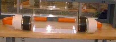
Acrylic Tank (a) |
1 |
30” x 8” x 15” |
|
Piping System (b) |
1 |
PVC pipes and fixtures |
|
Pool Pump (c) |
1 |
Teel; 1 ½ HP |
|
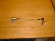
Propeller Assembly (d) |
1 |
|
|
Support Structure (e) |
1 |
Wooden |
|
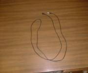
Wires (f) |
3 |
|
 a.
a.
 b.
b.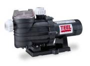 c.
c.
 d.
d.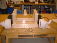 e.
e.
 f.
f.
DANGER: Do
not fill while plugged in to wall outlet. Risk of electric shock!!!!
CAUTION: Do not use pump prior to filling and do
not fully invert apparatus.
First, place the motor assembly through the wooden 1” hole. Then simply screw the 4” brass propeller into the shaft. After that release the motor mount onto the wooden support.
CAUTION:
Before connecting the motor assembly to the power supply make sure that
the power supply is off.
CAUTION: Make sure that the voltage dial is on zero (0) reading so that when power supply is turned on the propeller won’t start automatically.
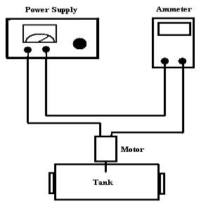
Figure 1 Wire setup of Apparatus
NOTE: For all procedures, tank and piping system must be filled with water from a near-by supply. A 120 VAC outlet is required for operation.
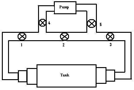
Figure 2 Piping and Valve assignments
1. Ensure system is wired in accordance with Figure 1.
2. The main pump will remain off.
3. The propeller will initially be stopped.
4. All valves will remain closed.
5. Receive data.
6. Apply full propeller power.
7. Slow propeller to stop when test is complete.
NOTE: Please reference Figure 2 for valve assignment.
1. Ensure system is wired in accordance with Figure 1.
2. The pump will initially be stopped.
3. The propeller will initially be stopped.
4. Valves 1 and 2 are one-sixteenth turn open.
5. Valve 3 is fully open.
6. Valve 4 is one-eighth open.
7. Valve 5 is fully open.
8.
Slowly increase propeller power until propeller reaches 55% full power.
WARNING: TURN OFF PUMP IF
TANK FLOW BECOMES UNSTABE OR UNCONTROLLED
9. While monitoring tank flow, turn on main pump.
10. Open valves 1 and 2 one-sixteenth turn.
11. Slowly open valve 4 less than one-sixteenth.
12. Open valves 1 and 2 one-sixteenth turn.
13. Close valve 3 one-sixteenth turn.
14. Alternate between simantaous opening of valves 1 and 2 with closing of valve 3 until desired flow is achieved.
15. Receive data.
16. Shut off main pump when test is complete.
NOTE: Please reference Figure 2 for valve assignment.
1. Ensure system is wired in accordance with Figure 1.
2. The pump will initially be stopped.
3. The propeller will initially be stopped.
4. Valves 1 and 2 are one-sixteenth turn open.
5. Valve 3 is fully open.
6. Valve 4 is one-eighth open.
7.
Valve 5 is fully open.
WARNING: TURN OFF PUMP IF TANK FLOW BECOMES UNSTABE
OR UNCONTROLLED
8. While monitoring tank flow, turn on main pump.
9. Open valves 1 and 2 one-sixteenth turn.
10. Slowly open valve 4 less than one-sixteenth.
11. Open valves 1 and 2 one-sixteenth turn.
12. Close valve 3 one-sixteenth turn. Alternate between simantaous opening of valves 1 and 2 with closing of valve 3 until desired flow is achieved.
13. Receive data.
14. Shut off main pump when test is complete.
NOTE: Please reference Figure 2 for valve assignment.
WARNING: TURN OFF PUMP IF TANK FLOW BECOMES UNSTABE OR
UNCONTROLLED
1. Complete Cruising Ship Checklist steps 1 though 15 to establish smooth flow.
2. Receive data.
3. Fully reverse propeller power.
4. Shut off main pump when test is complete.
5. Slow propeller to stop.
CAUTION: Do
not fully invert apparatus.
CAUTION:
Incline only to drain far pipes.
* Remove any remaining water with a sponge or paper towel
Links: Project Scope Final Design Report Final Design Presentation
Pictures Test Maneuvers Operation Manual