EXPERIMENTAL
APPARATUS
FOR
DEMONSTRATING DYNAMIC EFFECTS OF AN ELECTRIC DRIVEN PROPELLER

27 March 2003
Team 11: CAPS
Mitchell Quetant
Nathan Hammond
Adam Fisher
Sponosor:
Dr. Mischa Steurer
27 March 2003
Team 11: CAPS
Mitchell Quetant
Nathan Hammond
Adam Fisher
Sponosor:
Dr. Mischa Steurer
Figure
2: Wooden Support Structure
Figure
4: Piping System Schematic
Figure
5: Motor and Propeller Assembly
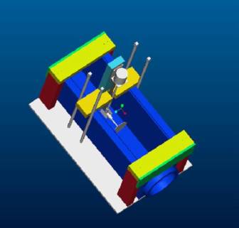
Figure
6: 3D Rendering of System
Figure
8: 3D Rendering of Tank
Figure
9: 3D Rendering of Motor Support
Figure 11: 3D Rendering of Wooden Support
This experimental apparatus was built to model the interaction water has on a ship propeller. Certain things occur when a ship is at sea are the rocking out of water, water rushing past the propeller at various speeds, and cutting through various types of debris. These types of events are going to reenacted through this apparatus. In addition, this experimental set up should be able to fit into a typical classroom. The main purpose of the system is to act a classroom demonstration for students and visitors to the Center for Advanced Power Systems (CAPS). Through it people may be able to gain a better understanding of types of research is taking place at CAPS.
The system consists of a 30” acrylic tank. Water will circulate through a series of PVC pipes from a pump. This will send flow across a 4” brass propeller. Different electrical signals will be monitored as the ship undergoes various maneuvers. The design process was long and hard, but the system is built and ready.
Since the propulsion system makes up a large
fraction of the overall power consumption of an electrically driven ship
accurate modeling of the dynamics and their effects on the overall system is
essential for the design process. Dynamic maneuvers such as reverse of
propeller speed or the propeller leaving the water in high waves are
significantly reflected in the signals, such as current, voltage drops, power
frequency, etc., of the electrical system. For example, during the crash
astern maneuver at full ship speed ahead the propeller transits through a
speed where the moving ship actually powers the motor until the propeller
comes to a complete stop. The power produced during this re-generative period
must be either dissipated in breaking resistors or absorbed by the rest of the
electrical system. During this transient, the generators may be forced to act
like motors with the prime mover as the load.
CAPS is therefore developing real time
hardware-in-the-loop simulation capabilities for electric ship power systems,
including propulsion systems. In our test bed, which will be functional by mid
of 2003, we will be able to simulate the dynamic torque loading on a test
motor during ship maneuvers such as the crash astern maneuver on a 5 MW power
level. However, no water and no real propeller will be necessary to accomplish
this. In this context, the experimental setup shall serve as a (portable)
display for an "open house" or for students and visitors of our lab
to emphasize our focus on electric ship propulsion. On a much smaller scale
and to a much more limited extend it should reproduce similar effects (e.g.
electrical current transients and the like) as an observed on real ships. The
real propeller operating in water shall help to explain some of the dynamic
processes in a very descriptive way.
This project’s objective is to design and build a scaled down apparatus of the motorized ship propeller underwater. This apparatus’ capabilities will span from measuring force to voltage, which will be measured by having sensors attached at key points in the model for accurate results. The preliminary purpose for this model is to be used as a display for the Grand Opening of the new CAPS Building in the Late March or Early April of the Spring Semester. The long-term purpose of this project is to allow for experimentation in measuring the various characteristics of the water acting on the propeller.
The initial tank and pump system was one that was rigid and extravagant. There were certain components that weren’t necessary and were later omitted. The initial tank design had dimensions that were quite oversized and unrealistic.
Several different tank designs were considered. One such design was a round donut shaped design that would have some variable radius and depth. Another consideration was a circular tank at variable depth and radius. The problem with these design the actual pumping of the water, which was found to be difficult and there would be lack of uniform flow. Uniform flow is an important factor for this project for purpose of receiving accurate readings and correctly mimicking the actual flow of water passing through a boat propeller. Consequently, the rectangular tank design was devised to control the flow of the water more efficiently. In essence, the tank would be structured similar to a wind tunnel but instead of wind, water will be used.
So, with more in depth research of this new design large designs were considered. The f the dimensions of the tank were 25” x 25” x 20”, similar to the size of a massive fish tank. After more research and calculations, it was found that this tank would be unrealistic and too much of an exaggeration for what was trying to be accomplished. The large tank would require a pump too large for practical purposes. In addition, there was a basic fluids concept that wasn’t considered in the building of tank. As water flows in the tank boundary layers form along the surface of the tank faces. These boundary layers can interfere with desirable uniform flow required to acquire ideal readings. Calculation 1 (see appendix) shows that with the propeller blocking a certain area of the water flow, the tank width should be approximately 8 in to arrive at the necessary uniform flow needed just around the propeller.
For the motor and propeller design, several different ideas were considered. The primary idea for the propeller was a trolling motor. Trolling motors are used for fish boats to maneuver around a lake or pond at slower speed than the actual boat motor. These trolling motor propellers had diameters of approximately 12 in., which is the reason for choosing such a large tank.
As part of the initial specifications, a lifting mechanism was to be designed. The design proposed was an automated screw lift that would elevate the propeller out of the water at various speeds. Other lifting designs were considered, such as a spring system, pulley system and manual lift.
After all possible ideas were exhausted for the project, a much smaller tankthan initially anticipated was required. In that, an 8”x 12” x 30” tank was built. This tank is small enough to be maneuverable and big enough to allow uniform flow across the propeller. The tank is made of acrylic. The ends of the tank were machined to conform to the fitting of 8” rubber flanges that would continue into the piping system that will be explained later. Figure 1 shows a picture of the completed tank.

The tank is constructed of ¼” acrylic sheets. The tank is bonded to together with acrylic solvent. This creates a bond that is actually stronger than the acrylic itself. The solvent actually melts the acrylic, which then harden to make the pieces almost act as one. Initially, all the pieces were cut to rough sizes with a band saw. An end mill used to finish the edges.
One of the biggest problems was machining the ends of the tank. In order to connect the rubber couplings to ends of the tank a 1.25” lip was needed. The lip was made of five sections of acrylic sheets that were glued together with the solvent. At first the section square. With a lathe the section were slowly rounded into 8.625” disk. The disk was glued to tank. Next a 7” hole was cut through a six pieces. This had to done twice. The process was very time consuming, and had to be finished before the rest of the tank could be constructed.
Detailed drawings of the tank and the individual pieces are included in Appendix C.
A wooden frame was constructed to ensure that the tank would remain structurally sound during operation. This wooden support scales the perimeter of the tank securing all of the most vulnerable point of tank. Though the glue used to construct seemed reliable, this wooden support was built as mainly a safety measure against any unforeseen occurrences. Figure 2 shows the wooden support by itself. The wooden support was made using typical 2 ½” wood screws, 2” x 4” wooden pieces, and two plywood end pieces.

Figure 2: Wooden Support Structure
Constructed completely out of 2x4’s, the wooden structure supplies a extra support for the tank. The wooden support will also have four wooden dowels (not shown above) to guide the motor in the lifting maneuver. (The lifting maneuver will be explained later.) Using wood make its construction rather easy. Unfortunately the 2x4’s make the structure somewhat bulky. Appendix C contains detailed drawings of the members, including their lengths and location of the pilot holes.
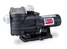
A TEEL 4RJ94 is being used a pump. This a pump used commonly in backyard pool and spas. With only a 1 ½ HP motor, the pump used in traditional wall outlet. This is important point. Initially pumps found in Florida State University surplus were considered for usage. Unfortunately, these pumps required a 220 V outlet, and thus a special box. The costs of the new wiring would more then out run the cost of the new pump. Even with the special outlet there was no guarantee the surplus pumps would still run. Below there is illustration of the actual pump used.
The purpose the pump in the project is to circulate water through the tank, so that it simulates a wind tunnel effect. The target water velocity was approximately 1 m/s. Given the size of the tank, the pump must pump 320 gpm. The TEEL pump can do that. Appendix A shows calculation of how that target flow rate was determined.
In order to circulate the water throughout the system, a piping system had to be devise to fit the specifications of the pump as well as the tank inlet and outlet. The piping starts from the outlets of the tank with an 8” rubber flanges that connect to the 8” to 4” reducer and then to the 4” to 2” reducer. All pipes used are schedule 40 PVC pipes and were glue together with PVC solvent and primer. From the 4” to 2” reducer starts the rest of piping system, where 2” pipes are used throughout. Valves are place at strategic positions in the system to toggle the water flow through the tank, without turning off the pump. These valves allow for optimal control of the flow. A bypass section was added to allow for the coasting test, where the propeller is moving while the flow to tank is ceased by closing valve 4 and 5. Valves 1, 2 and 3 can be used to throttle the flow throughout the system, and obtain desired flow characteristics. Figure 4 show how the pipes are orientated within the system, relative to the tank and pump.
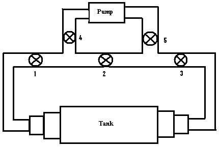
Figure 4: Piping System Schematic
To drive the propeller, a 12-volt DC motor was used, which is connected to a shaft that suspends down to the middle of the tank. This is where the propeller will be situated. The other end of the shaft is connected to a 90-degree bevel gear, which allows for the propeller to be positioned perpendicular to the water flow. This device is illustrated in Figure 5. A 4” brass propeller is used because it is sturdy enough to turn through water and light enough to achieve the desirable RPMs for various tests that are run. Plastic coupling and copper bushing were used to adjoin one shaft to another to attain the required length to suspend the propeller to the ideal position in the tank.
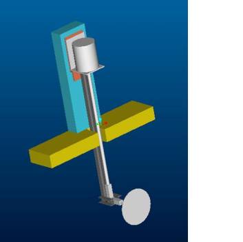
Figure 5: Motor and Propeller Assembly
A support structure was constructed to mount the motor and suspended the propeller in the tank. The support consists of a series of metal braces that help support the shaft band keep it straight. The braces attach a metal bracket. The bracket connects to the hardware that came with the motor as while as a piece of 2x4. The piece 2x4 serves to elevate the propeller the correct height in the tank. This will all connect to another piece of 2x4, which will rest on the tank. Appendix C has detailed drawing of all components of the motor support.
The system will under go series of maneuvers to monitor the effects each have on the motor. During each maneuver key electrical signals, such as current will monitored for changes. Below the maneuvers are briefly described. Descriptions of each maneuver can also be found at the Senior Design Team 11 website. Refer to the operation manual for a detailed description of the procedure of each maneuver.
The propeller will start with no water motion. The pump will not be used. The maneuver is an attempt to simulate what will happen a when first begins to start from a dead stop.
This maneuver will attempt to simulate how a electric ship system will react to changes in sea conditions will traveling in the open ocean. The pump will be running and the flow can varied using the valves.
This test has only the pump running. This will simulate a situation when a ship has cut power to its propeller, but still has momentum. The moving water can cause the propeller to spin. Readings can be taken to see is in current generated to through the propeller.
A ship in rough seas will at many points have its propeller come out of the water. The range in medium can have interesting effects on a spinning of the propeller, especially when it reenters the water. The test propeller will be lifted out of the water and then placed back in. Changes in current will be noted.
The crash astern maneuver refers to when a boat is traveling with forward speed. The propellers are then reversed in an attempt to stop. The reverse propeller motion combined with the ships forward momentum creates a regenerative torque that may be used to generated usable energy. This is the most important aspect and interesting part of the project.
Item
|
Unit
Price |
Quantity |
Price |
Vender |
|
Tank |
|
|
|
|
|
Acrylic
Sheets |
$74.91 |
1 |
$74.91 |
usplastic.com |
|
Acrylic
Solvent |
$10.75 |
1 |
$10.75 |
usplastic.com |
|
Plasticator |
$4.50 |
1 |
$4.50 |
usplastic.com |
|
Shipping |
$15.00 |
1 |
$15.00 |
usplastic.com |
|
Couplings |
|
|
|
|
|
8"x8"
Rubber Coupling |
$17.86 |
2 |
$35.72 |
Ferguson
Ent. |
|
6"x4"
PVC Coupling |
$10.26 |
2 |
$20.52 |
Ferguson
Ent. |
|
8"x6"
PVC Coupling |
$18.50 |
2 |
$37.00 |
Ferguson
Ent. |
|
Pump |
|
|
|
|
|
9600
GPM Teel 4RJ94 |
$390 |
1 |
$389.54 |
Grainger.com |
|
50"
Power Cable |
$89 |
1 |
$89.00 |
Grainger.com |
|
Propeller
System |
|
|
|
|
|
4"
brass blade |
$35 |
1 |
$35.00 |
harbormodels.com |
|
Johnson
Motor |
$30 |
1 |
$30.00 |
harbormodels.com |
|
Johnson
Motor Mount |
$10.00 |
1 |
$10.00 |
harbormodels.com |
|
4mm
to 5mm Coupler |
$11.00 |
1 |
$11.00 |
harbormodels.com |
|
6mm
to 5mm Coupler |
$11.00 |
1 |
$11.00 |
harbormodels.com |
|
Shaft
and Stuffing Tube |
$20.00 |
1 |
$20.00 |
harbormodels.com |
|
90
degree Drive Unit |
$69.00 |
1 |
$69.00 |
harbormodels.com |
|
Bushings
for Stuffing Tube |
$3.95 |
2 |
$7.90 |
harbormodels.com |
|
Shipping
1 order |
$9.00 |
1 |
$9.00 |
harbormodels.com |
|
Shipping
2 order |
$7.00 |
1 |
$7.00 |
harbormodels.com |
|
Piping
Equipment |
|
|
|
|
|
2"
Tee |
$1.05 |
2 |
$2.10 |
Home
depot |
|
2"
PVC Ball Valve |
$11.94 |
3 |
$35.82 |
Home
Depot |
|
2"x10'
PVC Pipe |
$3.94 |
2 |
$7.88 |
Home
depot |
|
4"x10'
PVC pipe |
$10.98 |
1 |
$10.98 |
Home
depot |
|
16
oz PVC PVC Solvent |
$2.98 |
1 |
$2.98 |
Home
depot |
|
16
oz PVC Purple Primer |
$3.96 |
1 |
$3.96 |
Home
depot |
|
Teflon
Tape |
$0.79 |
1 |
$0.79 |
Home
depot |
|
6
MIL Plastic Sheeting |
$9.47 |
1 |
$9.47 |
Home
depot |
|
4'
x 8' Plywood |
$14.59 |
1 |
$14.59 |
Home
depot |
|
2"x4" |
$2.87 |
3 |
$8.61 |
Home
depot |
|
2"
90 Degree PVC Joint |
$0.62 |
5 |
$3.10 |
Home
depot |
|
4x2
PVC |
$3.98 |
2 |
$7.96 |
Home
depot |
|
|
|
|
|
|
|
Total |
|
|
$995.08 |
|
Many hours were contributed to design and building of the system. Throughout people can gain better understanding of how the Navy will use electric ships. The different design iterations took time to final sort through, but the final design is the best and most practical. The system is durable and satisfies the wishes of the team and the customer. The different maneuvers show a variety of possible situations a ship may encounter on real ship.
Although the project is done there things that could be done to improve the system. Most future ideas revolve around automating many of the operations needed to conduct maneuvers. The motorized lifting for the propeller has already been designed. (See Appendix A) Ideally, the entire system could be controlled from a single operator’s panel. It was decided to focus more one the system itself than on automating it.
Planning a project of this magnitude was definitely new experience. This was the first time that I have had to go through the complete design process in such detail. Writing everything done was a key to getting lots of things done. Also remembering every detail keeps problems from arising later. Time is always much shorter than expected. I have gained a much better understanding what takes to be an engineer and design a system. Understanding and knowledge I will carry on to future situations.
This past year has truly been a learning experience for my group members and I. There are certain aspects about this year that affected me the most. For instance, I never knew how important communication is in industry. The common “word” has so much value, that it can make what you view as common sense, turn into a big disaster due a mere misunderstanding. If you had only communicated exactly what you wanted initially, setbacks can be avoided. In addition, I learned that persistence is the key to make people move for you. We were constantly following up with various vendors to check on our materials. Unfortunately, these vendors don’t have you as their #1 priority, so it was imperative for us to keep in close contact with them. So you have to be persistent with your business.
We the Senior
Design Team 11 would like to thank the following people for all of their
assistance in the completion of this project. Without these people this
project would not have been as much a success as it is. These people
are:
Dr.
Mischa it has been true learning experience for this past year. We all
encountered a lot of roadblocks (if you know what I mean), though they were
frustrating, we persevered through them together as a team. We would
like to thank you for your patience and understanding throughout this entire
endeavor.
Ant,
if it weren't for your various ideas and advise we probably would have strayed
in the wrong direction. You were able to explain everything so logically
and simplistically, and we really appreciate the time you took out to devote
time towards the completion of this project. Thanks!!
Keith
thanks for ALL of your ideas and recommendations for our project. Our
project would probably have been a total bomb if it weren't for your help in
the cutting and machining of various parts.
Cliff,
we would like to thank you for looking out for our safety throughout the
project. Sometimes we thought it was a bit of overkill, but after
looking at the overall scope of thing we understood where you coming form.
Thanks Again.
Though
we never really had too much interaction throughout the project, you came
right on time with your expertise on the electrical aspect of project.
Thanks for all of your help.
A full size propeller will work in the open ocean. The ocean can be considered an infinite medium considering its size. The model propeller must also work in a medium that can be assumed as infinite. The tank used to test the propeller must be made wide enough so that it will be outside the hydrodynamic boundary layer created by the flow. Considering a four-inch diameter propeller, the tank must be at least 8 inches wide.
A suitable size tank requires that the blockage area of the tank be no more than twenty percent of the total area of the tank. The blockage is defined as the ratio of the area of the propeller to the area of the tank
Calculation 1 starts with the diameter of the propeller and the blockage as twenty percent. Using the area of the propeller and the blockage the minimal area of the tank is found. From there the minimal width of the tank is found. Given a four-inch diameter propeller, the minimal tank width is 7.297 inches. The tank diameter is rounded off to an even eight inches.
A full size propeller attached to a boat moving in the ocean will be affected by the ocean water passing by it. A stationary model that has water flowing past it creates a similar effect. The flow rate that must be generated needs to be determined.
The flow rate of
the water is obtained from the desired water velocity and the area of the tank
as specified in Calculation 1.
Calculation 2 a flow velocity of one mile per hour requires a pumping capacity of 17,550 gallons per hour.
Calculation 3 shows the obtained velocity when using two pumps with
an output of 9600 gallons per hour.
A lifting mechanism is needed to pull the propeller in and out of the water. A power screw arrangement is used. The arrangement needs to produce fast dynamics to simulate the motion of a boat propeller moving in and out of the water in high seas.
Based on the lead of the desired power screw and a desired velocity the power of the motor is found. The lead of a power screw is the amount of linear travel obtained per revolution of the screw.
Calculation 3 dictates a motor output of 1440 rpm’s. This is based on a lead of ½ inch per revolution, and a lift velocity of 1 ft/s.
The required motor must also be able to apply the required torque to be
able to lift the propeller and its driving motor out of the water.
Using the lead and the weight of the propeller the amount of force and
the amount of torque needed to lift the propeller and its motor can be found.
Given a motor output of 1440 rpm found in Calculation 3 and a pitch diameter of .219 inches the lead angle and the corresponding force and torque found. The torque was found to b 0.011 ft-lb.
The required drive motor for the lift system would need to at a minimum be able to handle 0.011 ft-lb of torque at 1440 rpm’s.
It is of value to know by how the forces on the model compare to those that would be felt on the full size propeller on an actual boat. Since the scale model is of a similar shape as the full size it is possible to compare the forces through the drag coefficient. The value for each case will be the same. The drag coefficient is given below
Since the fluid is the same, the density in both cases will be the same. The ratio of the full drag force to the scale drag force can be found.
Calculation 6 the factor by which the scale force measured needs to increased by to give the actual force the full size propeller will feel.
Tank


Figure 8: 3D Rendering of Tank
Motor Support

Figure 9: 3D Rendering of Motor Support
Wooden Support
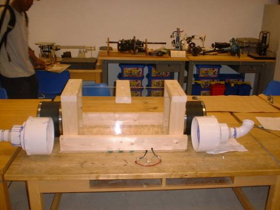

Figure 11: 3D Rendering of Wooden Support
D.
Project Management
Article
I
Attendance and Punctuality
Section 1 – Attendance. Each group member is obligated to attend every group meeting.
Section 2 – Absence. Each group member is entitled to call the other group informing them of their absence.
Section 3. – Punctuality.
Punctuality is expected out of every group member, and if you are going
to be late, be sure contact one of the group members to inform them of such.
Article
II
Assignments/Presentations
Section 1. – Assignment completion. Every assignment needs to be complete by 12:00pm Wednesday night, to be turned in the next day.
Section 2 – Duties. Each group member always shall be given a specific task relative to a certain assignment.
Section 3 – Group Compliance.
All assignments have to be to the satisfaction of the all the group
members.
Article III
Section 1 – Respect. As a member of this group, you must respect your group member’s ideas and opinions.
Section 2 – Customer correspondence. The customer shall be contacted at least once a week or as needed by the group.
Section 3 – Meetings. The group shall meet twice a week, once in the beginning of the week and one at the end of the week.
C.A.P.S Team 11 meets Monday at 12:30pm on a weekly basis at the FAMU-FSU College of Engineering Building B in front of the Cafeteria. Some of the things that are done at these weekly are:
- Delegate duties to each member to have ready by Wednesday for review
- If possible, additional brainstorming and concept generation commences
- If possible, contact our customer to find out any new developments in the project scope.
Establish another meeting time
during the week, if needed. Most
likely, they will be on Wednesday
|
Name |
Email |
Phone
Number |
|
Project
Sponsor |
|
|
|
Mischa
Steurer |
steurer@caps.fsu.edu |
(850)
644-1629 |
|
Project
Assistant to Sponsor |
|
|
|
Anthony
Gleaton |
agleaton@eng.fsu.edu |
(850)
644-1629 |
|
Thomas Anthony |
anthony@eng.fsu.edu |
(850)
591-6599 |
|
CAPS
Team Engineers |
|
|
|
Adam
Fisher |
amf0870@garnet.acns.fsu.edu |
(850)
504-1149 |
|
Mitchell
Quetant |
mquetant@eng.fsu.edu |
(850)
443-2177 |
|
Nathaniel
Hammond |
nhammond@eng.fsu.edu |
(850)
422-2177 |
|
Course
Professor |
|
|
|
Cesar
Luongo |
luongo@magnet.fsu.edu |
(850)
644-1095 |
|
Item |
Projected
Price |
Overall
budget |
|
Tank |
$200 |
|
|
Propeller |
$50 |
|
|
Motor |
$100 |
|
|
Lifting
and Mounting Mechanism (total) |
$300 |
|
|
Pumps |
$500 |
|
|
Pipes |
$150 |
|
|
Fixtures |
$50 |
|
|
Total |
$1350 |
$3,000.00 |
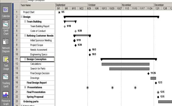
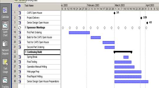
Our work breakdown structure itemize all of the
duties involve with the completion of this project from beginning to end.
This structure has been followed to some extent, yet there have been some
modifications to what stated and actually done.
This same structure is delineated in the hypothesized project plan.
The actual project plan will give the events that took place during the
project design work.
|
Activity |
|||
|
1.0 Design |
|
|
|
|
|
1.1 Teambuilding |
|
|
|
|
1.2 Refine customer requirements |
||
|
|
|
1.2.1 Initial meeting |
|
|
|
|
1.2.2 Concept presentation and discussion |
|
|
|
|
1.2.3 On-going feedback sessions |
|
|
|
1.3 Product evolution |
|
|
|
|
|
1.3.1 Concept selection |
|
|
|
|
|
1.3.1.1 Initial concept generation |
|
|
|
|
1.3.1.2 Concept elimination |
|
|
|
|
1.3.1.3 Concept merging |
|
|
|
1.3.2 Design refinement |
|
|
|
|
|
1.3.2.1 Calculations |
|
|
|
|
1.3.2.2 3-D Computer model |
|
|
|
|
1.3.2.3 Technical drawings |
|
|
|
|
1.3.2.4 Material selection |
|
|
|
|
1.3.2.5 COTS selection |
|
|
1.4 Purchase orders |
|
|
|
2.0 Fabrication |
|
|
|
|
|
2.1 Initial build |
|
|
|
|
|
2.1.1 Parts assembly |
|
|
|
|
2.1.2 Procure bits and pieces |
|
|
|
2.2 Initial run-up |
|
|
|
|
2.3 Optimiztion and refinement |
|
|
|
|
2.4 Final product |
|
|


Links: Project Scope Final Design Report Final Design Presentation
Pictures Test Maneuvers Operation Manual
Contact & Profile Page Project Poster Acknowledgements