Test Summary and Results
Static Tests Wire Test Analysis Mandrel Adhesive
In preliminary test design, the team believed it would have to perform both static and dynamic tests to determine the success of the wire in a test situation; however, further research and discussions with our advisors at Eglin AFB revealed that the time relevance in which the wire experiences the force until detonation of the projectile can be calculated as a static force. Rather than having to use a modified charpy test and perform the dynamic test, the team only had to perform static testing with the Tinius-Olsen stress machine. The machine simulates the force the wire would feel as the parachute deploys and unwinds the spool. The voltage drop is measured across the wire or cable to determine when the wire fails to continue transmitting information as the specimen is stretched in the machine to determine its ultimate tensile strength.
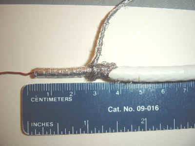
The first static test performed was a failure. The wire being tested was clamped directly into the machine using the clamps for the testing of metal specimens, and the machine was turned on. Rather than testing and stressing the wire as the team anticipated, the machine began to strip the wire layer by layer. First the outer shield was broken, then the braided shield was unraveled, the insulation was torn, and finally the wire itself was broken. As this is not how a wire will perform under actual conditions, a testing apparatus had to be design to hold the wire as it is being stressed. The following picture (figure 1) shows the wire after initial static test.
For the second static test attempt a pulley system of clamps was machined to hold the wires and cables as they were tested. The test apparatus was then screwed into the top and bottom of the Tinius-Olsen test plates. The wire being tested is threaded through the pulley system on top, down into the test region, and then threaded through the pulley system on the bottom. The pulleys provide a larger region of surface area where the wire can be held in place and distributes the contact force over a larger area so as to prevent slipping of the wire during testing.
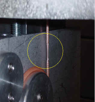
The team only had to make a minor adjustment to the second static test in order to correct the slipping problem. Rather than just threading the wires through the pulley system once, they were wrapped two times around each of the circular clamps. When this was done the team was finally able to successfully test each of the seven wires. The wires broke in the test region as they were expected. In figure 2, a successful wire fracture is shown.
It was predicted that the two wires which would be successful for possible implementation in the projectile would be the RG142 coaxial cable and the Beldin 10 strand copper coated steel wire. These wires would be offered as a solution depending on whether Eglin AFB would like to be able to use a communication wire that is readily available on the market (RG142) or a wire that had to be specifically manufactured for use in the mandrel communication system (Beldin 10 strand). Testing revealed that the RG142 wire would not be successful in practical application, thus the only wire Eglin AFB will be able to use at this time is the Beldin 10 strand wire. A graphical comparison of the theoretical force the wire will experience and the actual ultimate tensile strength is illustrated in figure 3.
To meet the needs expressed by our advisor at Eglin AFB, the Beldin 10 strand copper coated steel wire must be used in the communications system. The wire has a Kevlar strand running through the wire to increase the tensile strength of the wire, and the steel contributes to the strength. The copper coating on the wire insures that the wire has a good conduction quality. The wire is only expected to experience force of 100 lbf, and has an ultimate tensile strength of 613 lbf. The conducting wire is not expected to break until the ultimate tensile strength is reached, thus the wire should not have problems with failure of signal conduction. Should the wire experience a force higher than the one predicted, there is still enough of a safety factor in the wire that it should not fail during communication with the launching aircraft until detonation of the projectile.
The only drawback to using the wire is that if the communication length exceeds 400 ft then the conduction rate becomes severely lowered. The Kevlar strand causes a static charge to build up in the wire and effectively blocks conduction of the signal. As the wire is only expected to be needed in a 200 ft length the static charge build up should not have a significant effect on the conduction rate for this application.
After analyzing the current design, it was thought best to stay with a cone shaped mandrel. Then after finding the theoretical forces that would be applied to the wire, it was brought to our attention that a very strong wire would be needed. After doing so more research, it was evident that the minimum bend radius would be larger for higher strength coaxial cables, which in turn meant that the base of the cone shaped mandrel would be very large. Knowing the space constraint and the amount of wire needed meant that reevaluating the cone shaped mandrel was necessary. The design would still have no moving parts because the best way to control the unspooling of the wire was with the speed of the projectile. This led to the question of shape again. The only real choices that were clear were either the cone or cylinder shaped mandrel. The cylindrical shape would cause more friction, but the cone shape utilizes too much space. Well, another way to reduce friction is to eliminate any rubbing of wires together. The answer was simple: change the method of spooling the wire. If the wire could be spooled in a way that it would not run over itself when it unspoiled then there would be no problem with a cylindrical mandrel.
The major flaw of this geometry is that as the wire unravels from the spool body, it rubs against the wire that it is wrapped around. This unnecessary friction leads to undue stress on the wire, which may lead to transmission failure. Currently, the wire is wound from bottom to top, and then brought back down to be wound from bottom to top again. This is repeated as needed. This method produces an increase in acceleration (jerk) each time the wire is sent back to the bottom. As the wire reaches the bottom, it will change acceleration again. Having the wire wrapped in this fashion produces extra force that can cause failure of the wire.
These two problems were remedied by changing the geometry of the mandrel and the orientation of the wire. The new design calls for a cylindrical mandrel, which has a slope of one. The diameter is limited to the minimum bend radius of the wire chosen and the diameter of the wire exit in the tail kit. As for the wire, the "platter theory" (aka pan cake method) will be employed, it will be unwound in layers from top to bottom. This can be seen in Figure 4. This reduces friction between the wire and the body significantly because the wire, in theory, will be going straight up; therefore the only resistance would be the silicone used to hold it in place.

The wire has to wound in platters and stacked on top of itself. To be the smoothest unwinding possible, the wire cannot be wound in to out every time. This would cause a jump in acceleration or jerk. The first plan to accomplish this form of spooling was to fabricate a spiral slotted disk. A first platter needs to be wound against the base plate of the mandrel first. Then the slots would be filled with a divider that the wire would be wound between from the outside of the disk in. Once the center of the disk was reached, the disk would slide onto the mandrel and leave a neatly stacked second platter places on the first platter. These two steps are then repeated until the required amount of wire has been spooled. In the end, it was found easier to just hold the wire in place while it is being spooled. The spooling technique used in this projects requires two team members to spin the mandrel around and guide the wire into place with their hands, which will be covered in adhesive to make the wire stay put. When the wire is completely wound, the spool is taped to the mandrel until the adhesive dries. At this point the spool can be slid off the mandrel or kept on if that is convenient.
Since the wire chosen was the one given to the team by Eglin, it was assumed that the wire has a mandrel to fit its minimum bend radius somewhere at Eglin. With this in mind, the mandrel was machined bigger so it would be easier to see the wire unspool, easier to spool, and less expensive to make since the metal pipe used was free.
The uncoiling test is conducted to assure the sponsor that the mandrel design functions correctly. The wire was wound around the mandrel as described above and above three feet of wire was not mounted in the spool. The end of that three feet was threaded through one of the cylinders on the wire test fixture and clamped secure. The mandrel was then held upside-down by the base plate over the edge of a building. The wire test fixture was dropped and the wire began to unspool. The building was estimated to be ninety feet high and the force of gravity accelerated the wire at 32.2 feet per sec squared, which at most would give the wire a velocity of 90 feet per sec. It is understood that this speed will not exert the force sought after, but the static test proves the wire will with stand the force and the uncoiling test shows that the design will keep the wire from tangling so it will experience such high-speed forces.
The mandrel is only part of the spooling process, since it forms the wire, but it will not hold it there. The wire has to be held together so that it does not unravel when taken off the mandrel. Used here is a RVT 21 silicone (Please see figure 5 below). The advantage of using silicone to hold the wire is that it will not act as a typical adhesive. The only way it can is when it is applied to another prepared and primed silicone product, in which case provides a more than average glue. The grade used was called RTV 21. It is a pink viscous liquid around 26,000 centipoises (cps). At warmer temperatures it will setup and harden over time; therefore it is advantageous to store it around 0 degrees Celsius.

Typical applications of the silicone compound include gaskets and molds, release applications, and encapsulating electrical coils. The last two applications will be the typical for said mandrel/ spool. One important property is that it is FDA approved for food contact applications. This is important to the technician who will be handling the silicone. However, proper safety precautions should always be observed when handling solvents.
At the time of application, a hardener is added to speed up the cure time to be fully dried in 24 hours, but dry to the touch in 1 hour (1 hour is base on correct ratio of silicone to curing agent). The hardener is called Dibutyl Tin Dilaruate. The recommended ratio is 0.5% curing agent of the total weight of RTV 21 silicone used. In the project 100 grams of silicone is needed and 25 drops of the curing agent should be added per spool to be made. If setup time needs to be lengthened then 0.1% of the curing agent is added or 1 drop per 100 grams RTV 21. When mixing, care should be exercised because the silicon (RTV 21) is so viscous, air bubbles may form. This is more evident as the given setup time of one hour decreases. One remedy is to fold the mixture instead of stirring or shaking. If bubbles persist, a vacuum of 25mm Mercury should be applied to the solution. No such problems occurred during application. In the need of quick removal, turpentine can be used to remove the silicone, but a less toxic way would be to just let it dry and then rub or scrap off any excess. Of course, when used as an adhesive, the latter will not work.
|
|
|
Team Members/Sponsor Project Scope Background Info
Test Summary and Results Related Links
