|
|
|
|
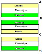
a. Fuel Cell StackThe fuel cell stack consists of three fuel cells. The design of the stack explains the fuel cells’ orientation relative to one another. A few designs were developed and then a decision matrix was used to make the final selection. The first design, as shown in Figure I‑1 is more traditional. It simply stacks the fuel cells on top of one another, front to back. This design would require 3 air inputs/outputs and 3 fuel inputs/outputs. Air must run over all of the cathodes and fuel must run over all of the anodes.
Figure
I‑1:
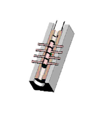
Design 1 The second design is a modification of the first. It stacks the fuel cells back-to-back to simplify the gas inputs and outputs. Air can run through one channel and hit the cathode of two fuel cells. The fuel can also be channeled to run over the anode of two fuel cells. Overall, there would be 2 air inputs/outputs and 2 fuel inputs/outputs. Design 2 is shown in Figure I‑2 . b. Fuel Cell HousingThe original design for the fuel cell housing used an alumina tube with holes drilled perpendicular to the axis of the tube for the gas inlets and outlets. This design, along with what it would look like as a full assembly, is shown below.
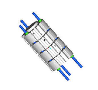
After careful analysis of this design, it was determined that the incoming gas flows would need to be heated in order to minimize any potential temperature gradients in the system. We decided to look at an alternate method of using a machinable ceramic so that we would have more freedom in the design and so that the gas flows could run along the axis of the heater. The final design is pictured below.
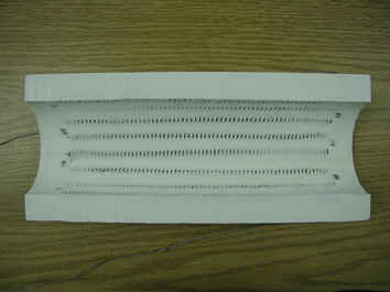
c. Heating SystemWe considered a number of different methods to provide the heat input to our system. They included, using a Bunsen burner or propane torch, placing the system inside a cylindrical heater, and using a furnace. The open flame idea was ruled out because of the temperature fluctuations that might arise in the system and also because of safety. The furnace idea was ruled out because this would confine our testing system to a lab and this would not satisfy the mobility requirement of the system. Finally, it was decided that we would use a semi-cylindrical ceramic heater manufactured by Thermcraft, Inc. This heater provides uniform heat input, is easily controllable, and allows the system to be portable. The heater we are using is pictured below.
d. Electrical SystemIn order to collect the electrical output of the fuel cells, we needed a connection to the anode and cathode that is conductive, resistant to heat and corrosion, and priced within reason. The original idea consisted of a simple connection of a single wire to each side of the fuel cell, leading to the external circuit. It was then discovered that the resistance of a single wire could possibly hinder the flow of current from the cell, thereby affecting the performance of the system The solution to this problem was to use a wire mesh that could be placed on both the anode and cathode to collect electrical output. The mesh has the advantage of providing an increased surface area for conduction while at the same time leaving ample space for the reaction to take place.
To transition from the mesh to the external circuit, holes are drilled in the fuel cell housing to allow a temperature and corrosion resistant Inconel wire to connect the mesh to the external circuit. LINKS Thermcraft Inc. High Temperature Heaters
|
|
|