|
|
|
|
a. Fuel Cell HousingThe requirements of the fuel cell housing are to support the three fuel cells and the gas delivery system. The housing should be easy to manufacture and minimize costs. Standard dimensions will be used to further in cost reduction and ease in the manufacturing process. The housing should also be able to support sealing elements. Sealing is needed to keep the fuel and air from interacting. Material selection played a huge role in designing the housing for our assembly. The housing material must meet many critical requirements. First and foremost, the material must be able to withstand high temperatures. The fuel cells need to heat up to a minimum of 800°C. The system can operate up to 1000°C for increased ionic transportation. The material must be dense so that the fuel and air will not diffuse through it and interact. It must also be resistant to corrosion and oxidation and affordable. From looking at materials charts and consulting with our sponsor, Dr. Gielisse, a ceramic material was our only option. The ceramic material Alumina was chosen for our design. Alumina met all of the above requirements and came in sizes that fit our needs. A basic housing design was made based on the geometry of the fuel cells. Each cell is going to be supplied by the Materials Science and Engineering Department. The basic concept of our design is to have ceramic tubing that consists of four modular parts. In between the different ceramic parts rests a fuel cell, gaskets, and the electrical connections. Holes drilled axially allow for gas flow over the fuel cell faces. Gaskets are being used in between the fuel cells and the ceramic housing to create a compression seal. The ceramic housing also has holes running perpendicular to the axis for the gas inputs and outputs. Figure I‑3 depicts the modular component. After all of the components are stacked together, they are compressed with a clamp to create a seal and hold the parts together. This assembly rests inside of a cylindrical heater. The gas inputs and outputs rest on the sides of the heater, running perpendicular to the heater and ceramic housing. All of these components would then be surrounded by insulation. Figure III-4 shows this full assembly.
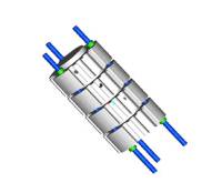
Problems arose with using Alumina after it was determined that the incoming gas flow would need to be heated. The gases need to be warmed up to a temperature that does not create a large temperature differential at the fuel cell interface. Recall that the fuel cells are operating at temperatures around 800°C. By flowing room-temperature gas over the cells, cracking could occur within the fuel cells or the Alumina due to their brittle nature. The solution to this problem is to run the incoming gas parallel to the heater’s axis in the extra space. There is about 6” of unused space in the heater due to the size difference between the fuel cell housing and the heater. Changes in the orientation of the gas inlets and in the fuel cell housing would have to be made to accommodate the new configuration. Another problem with the previous design was that it lacked ease of assembly. All of the components would have to be stacked and aligned using only human judgment. The clamp would somehow have to be put on the assembly without any of the parts moving around. If there is any misalignment between the fuel cells and housing then sealing problems arise. The only solution to these combined problems was to find a machinable ceramic for implementation in the fuel cell housing unit. This type of material would allow for a more detailed design. A ceramic known as 902 Alumina Silicate is manufactured by the Cornices Corporation. This material can operate at temperatures up to 1150°C, can be machined with standard equipment, is resistant to oxidation, is dense, and affordable. It meets all of the basic requirements and had the added benefit of being machinable. From here, we went on to design detailed modular components. The size of each component stayed the same as in the previous design. There are many added features to this design. Each part is a male/female piece. It accommodates the gas supply tubing by having grooves along the outer diameter. Threaded rods will be inserted in three equidistant holes and used to compress the assembly. Nuts will be tightened on both sides of the rod to actually compress the assembly. The fuel cell housing will again be placed inside a heater and surrounded by insulation. Figures II-5 and II-6 show the ceramic tube geometry and the housing with compression rods, respectively.
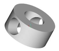
Figure II-5: Original ceramic tube geometry
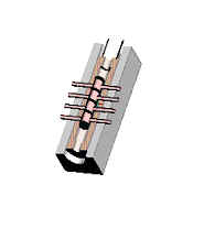
Figure II-6: Original design for fuel cell housing, heater, and insulation Problems arose with using Alumina after it was determined that the incoming gas flow would need to be heated. The gases need to be warmed up to a temperature that does not create a large temperature differential at the fuel cell interface. Recall that the fuel cells are operating at temperatures around 800°C. By flowing room-temperature gas over the cells, cracking could occur within the fuel cellsor the Alumina due to their brittle nature. The solution to this problem is to run the incoming gas parallel to the heater’s axis in the extra space. There is about 6” of unused space in the heater due to the size difference between the fuel cell housing and the heater. Changes in the orientation of the gas inlets and in the fuel cell housing would have to be made to accommodate the new configuration. Another problem with the previous design was that it lacked ease of assembly. All of the components would have to be stacked and aligned using only human judgment. The clamp would somehow have to be put on the assembly without any of the parts moving around. If there is any misalignment between the fuel cells and housing then sealing problems arise. The only solution to these combined problems was to find a machinable ceramic for implementation in the fuel cell housing unit. This type of material would allow for a more detailed design. A ceramic known as 902 Alumina Silicate is manufactured by the Cornices Corporation. This material can operate at temperatures up to 1150°C, can be machined with standard equipment, is resistant to oxidation, is dense, and affordable. It meets all of the basic requirements and had the added benefit of being machinable. From here, we went on to design detailed modular components. The size of each component stayed the same as in the previous design. There are many added features to this design. Each part is a male/female piece. It accommodates the gas supply tubing by having grooves along the outer diameter. Threaded rods will be inserted in three equidistant holes and used to compress the assembly. Nuts will be tightened on both sides of the rod to actually compress the assembly. The fuel cell housing will again be placed inside a heater and surrounded by insulation. Figures II-5 and II-6 show the ceramic tube geometry and the housing with compression rods, respectively.
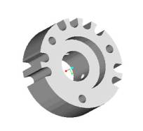
Figure II-5: Final design for subassembly piece
Figure II-6: Final design for housing including compression rods
|
|
|