[ Production Process ]
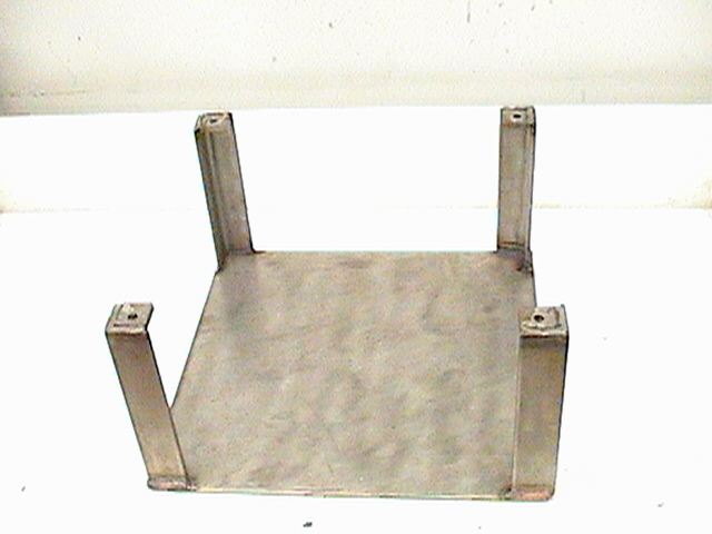
Step 1: cut down the base from last years project.
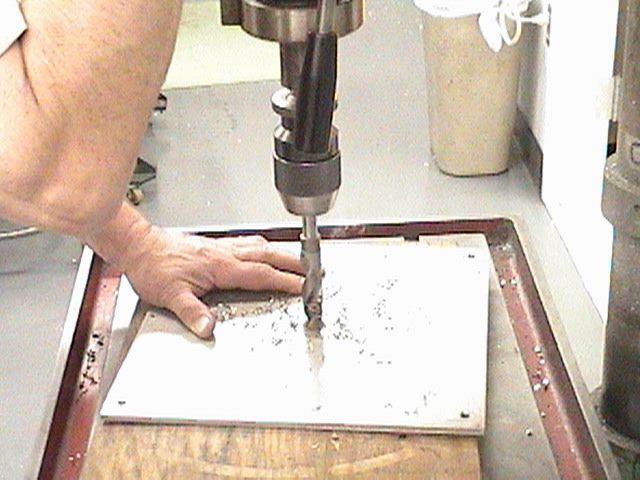
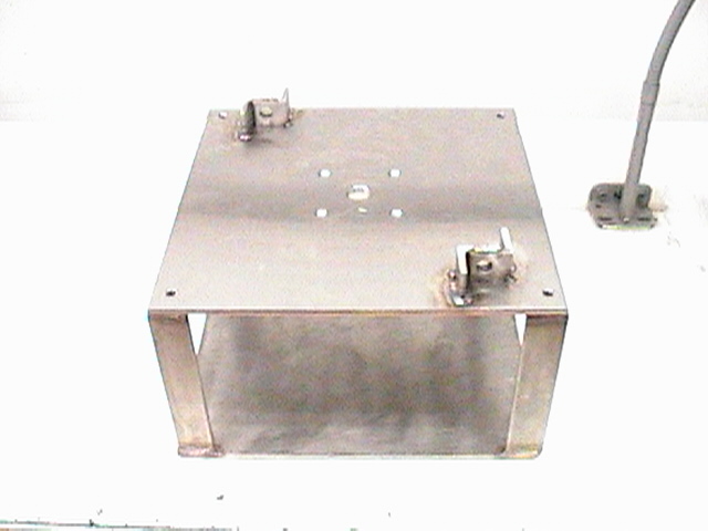
Step 2: Take the top plate to drill holes for the motor shaft and screws.
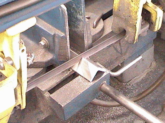
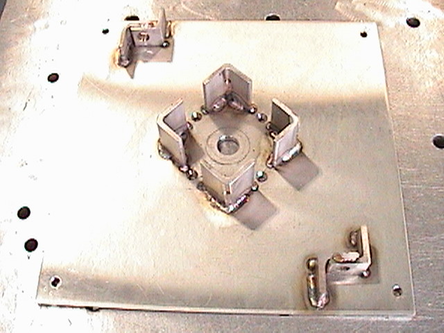
Step 3: Use pieces of the old base to fashion this notch that will be welded on the top plate.
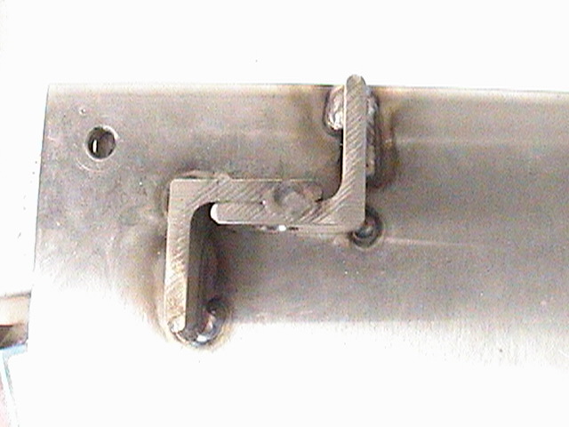
Step 4: These notches will hold up the actuators and are positioned so objects (actuators, shaft, etc.) on top do not collide.
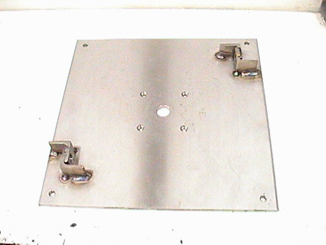
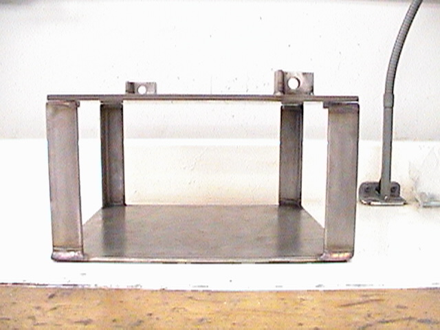
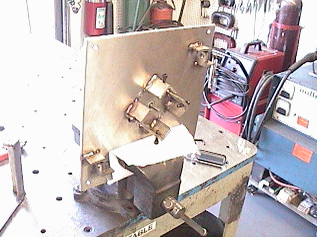
Step 5: Place the two pieces together.
Step 6: Check out if both pieces align up correctly and mark the holes.
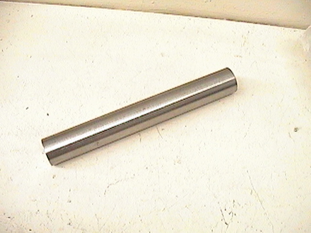
Step 7: Like the support columns, cut down the center shaft to fit our specifications.
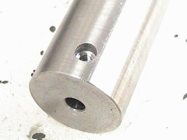
Step 8: Drill a hole for the motor shaft, just deep enough so it doesn't touch the plate. Tap another hole for a set screw.
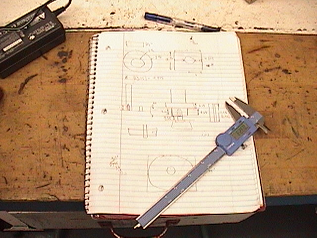
Step 9: Break out the paper and pen, to lay out the next plan of attack.
Step 10: Cut out some more pieces from the old base to make a support cast for the bearing.
Step 11: Set up a mock bearing cast in order to get a idea on how it will look.
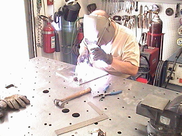
Step 12: Weld to the top plate.
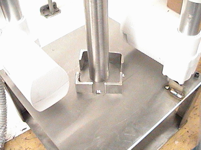
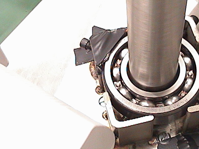
Step 13: Check out the bearing housing for clearance. and drill holes for set screws.
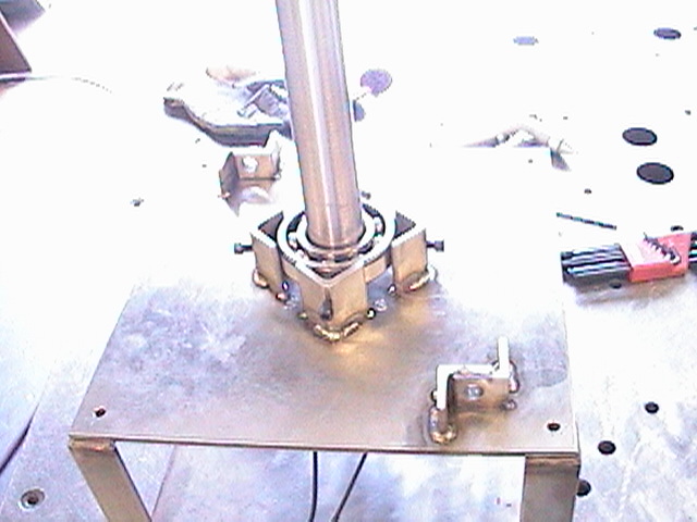
Step 14: Put in the bearing set screws and install the motor.
Step 15: Use the hydraulic press to attach the center shaft to the bearing (not show). Then put it in the housing.
Step 16: Attach the actuators and all the nuts that are needed.
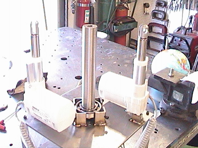
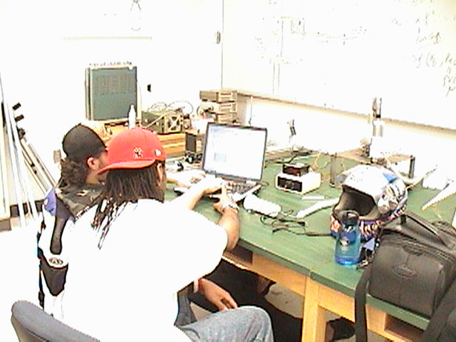
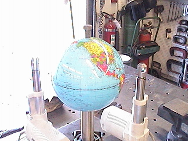
Step 17: Set up the system to run thermodynamics test. Four Thermo-couples are placed in key places
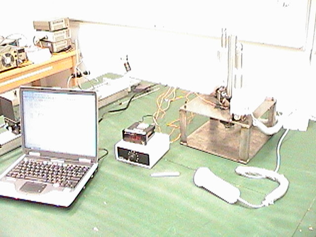
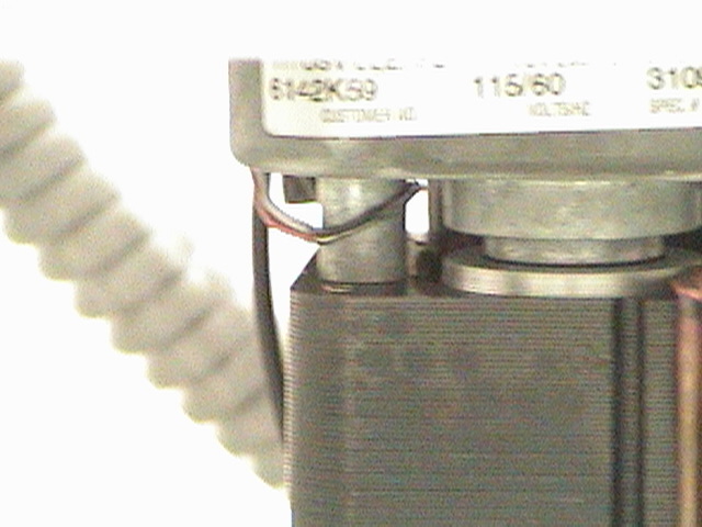
Step 18: One right on the motor
Step 19: Between the shaft and top plate
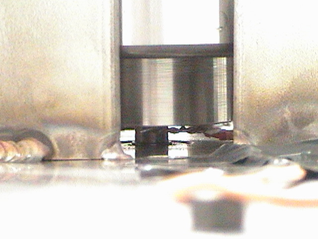
Step 20: Directly on the surface, just outside the bearing housing.
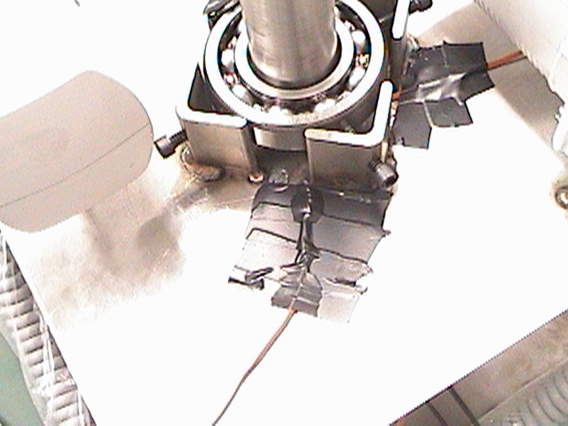
Step 21: The last on the outer ring of the bearing
Step 22: Run the system for two hours and recorded the results. Once that was done, start with the display.
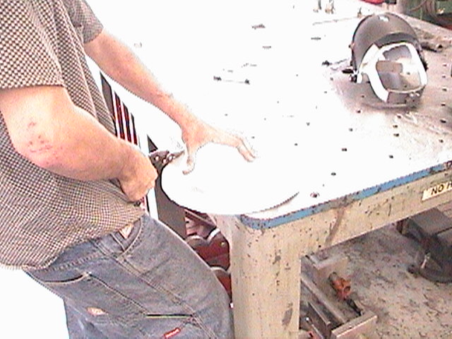
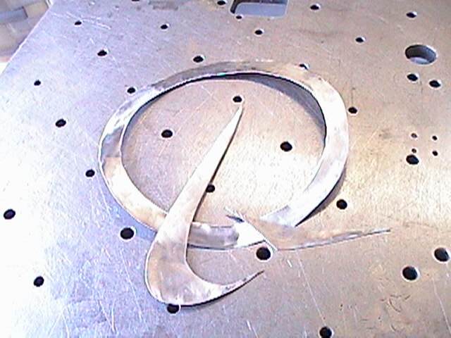
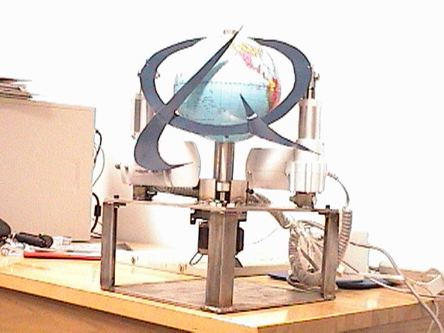
Step 23: Start cutting out the Boeing halo symbol with the plasma gun for the display.
Step 24: Polish the sheet metal weld them together.
Step 25: Place the globe on the shaft.
Step 26: Spray paint the sheet metal and mount it on the system.
[Home Page] + + [R & D] + + [Back to Top]