Design
The filters are flowing systems hosed within a plastic container with a layer for gas dispersion. A layer of crushed clay, gravel, sand, and wood chips will follow. "For the forcing of air that may be necessary at times, a fan powered by a solar panel was connected in order to maximize the filter's self maintenance capabilities. Figure D-1 below shows a general schematic of the filtering system, including the main components.
Figure D-1. Schematic of the initial Filter Design
After numerous designs and redesigns we were able to combine the objective of the project with wants and needs of our supervisor and customer. All components were made while keeping in mind the necessity for the filter to be heavy duty, able to withstand changing weather or climates, and low cost. Below are the actual Pro E solid models for the final design.

Figure D-2. Plastic Housing
The housing was made from a plastic barrel purchased to fit our desired specifications. The housing is used to house the compost while its lid was designed to measure the flux of methane being emitted. Before use while the filter is empty and during use in order to calculate the filter's actual methane reduction. Note the fins within the housing used to prevent outer escape and promote even distribution throughout the methane layer.
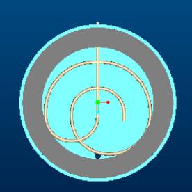
Figure D-3. Housing with Copper Tubing Diffuser
An aerial view of the filter housing shows the fins and most importantly the copper tubing diffuser. Instead of creating a custom diffuser to evenly distribute the methane entering the filter, a copper tub was rolled and holes were drilled in it to allow gas to circulate. The bottom of the filter housing was also drilled and a drain plug was inserted to give easy access when draining is necessary. Not shown in this picture are the gravel and rocks, thin diffuser filter, and compost. The rocks and gravel lye on the bottom of the housing to support the copper diffuser and compost. The diffuser filter restricts compost from clogging the wholes of the diffuser.

Figure D-4. Wooden Base
A structurally sound base was created for multiple reasons. The first and most important reason was to support the massive weight of the bio-filter once filled with compost. The nearly 3 foot layer of compost and housing was calculated to weigh 200 kilograms when full. The base was vital also because of a possible need to drain the filter at random times, after rainy weather, due to the filter remaining open at all times unless testing.
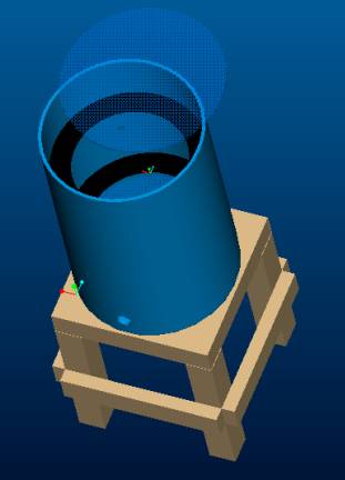
Figure D-5. Filter Final Design and Assembly
The finished bio-filter will stand at the landfill and will only require weekly to monthly maintenance. Not included in the solid model drawings is the actual hose and landfill ventilation adapter. These two components are based solely on the landfill's particular ventilation system.