|
Mechanism Description
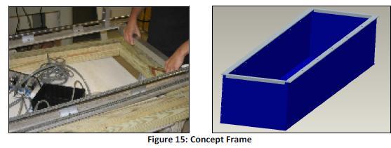
To keep the rigidity of the apparatus, an aluminum drop in frame was designed to fit on the
top of the box. It was designed using two pieces of ( ½’’ x 2 ½’’ x 96’’) and two pieces of ( ½’’ x 2’’
x 23’’) that were welded in a square shape. Along the two 96’’ bars, hole patterns were drilled
every 13’’ so that steel rod supports could be fastened to them using 8/32 button head screws.
The aluminum for this frame will be provided by Eglin Air Force Base, as well as the machining time.
3.1.1 Motion in the x-direction
To constrain the motion along the x-axis(8ft length), two ¾’’ rods made of hardened steel
are mounted on top of the drop in frame by their shaft supports. A bearing block, which is
mounted on the side of the apparatus, where the chain is, consists of two linear bearings that
allow for the motion along this x-axis. Initially, the same type of bearing was mounted on the
opposite side of the apparatus; in this case binding was a big factor. If the apparatus was moved
slightly in any way, it locked up and was unable to move.
Due to Binding, a new piece was designed, that consists of a bearing block similar to the older
version, but instead uses a roller bearing that will roll on top of the shaft and allow for slight
movements made by the apparatus. Binding was eliminated with the new piece.
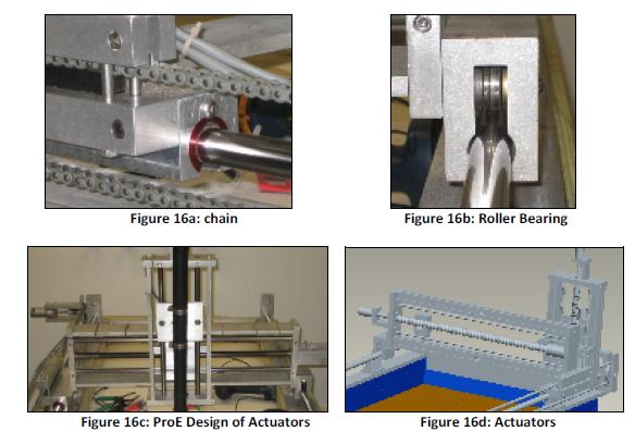
In order to produce the motion along the x-axis a chain and sprocket method was used.
Approximately sixteen feet of chain was needed as well as two corresponding sprockets which
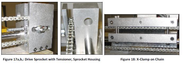
were mounted to (1” x 2” x 3”) aluminum bar. A groove has been machined into the bar to allow
for proper fit of the chain and tension in the design. The drive sprocket, as seen below in Figure
17a, is machined with bearings that are mounted rigidly into the sprocket housing, Figure 17b.
This was designed in order to make sure that the chain has no chance to pop off or come loose
while being driven. The Sprocket housing was also designed with a tensioner to keep the chain
in tension. As seen below, the sprocket was machined with a groove to slide back and forth,
with a set screw perpendicular to the sprocket to screw or unscrew the sprocket position for full
tension. The chain transfers motion to the y-actuator by means of a clamp that is made with the
same teeth pitch as the chain. This grabs the chain with the teeth and holds it in place as seen in Figure 18.
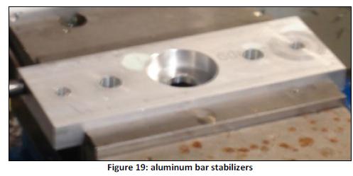
3.1.2 Motion in the y-direction
An actuator frame consisting of two pieces of ½’’ by 3’’ aluminum bar stock, cut 24” in
length creates a motion in the y-direction. These pieces of aluminum are flanked by two more
pieces of 5/8” x 1 ¼” x 2 ½” aluminum bar and secured with ¼ -20 socket head screws. As seen in
Figure 19, the aluminum bar ends have holes drilled for added stabilizers and bearing mounts.
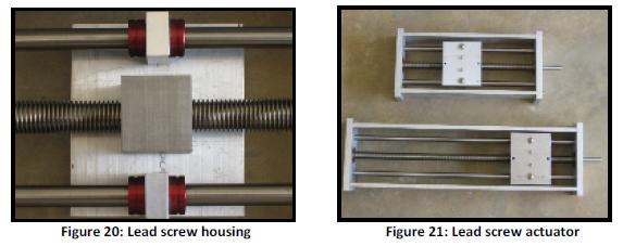
In order to produce the back and forth y-actuator motion, steel ACME threaded rod (a type of
precision rod that can be used as a cost effective alternative to a lead screw), purchased from
McMaster Carr, will be used the rod selected is a ¾” -10 that is 20” in length. Corresponding
bronze lead screw nuts were required. Figure 20 shows a custom housing for the lead screw
nuts which will then have a mounting plate attached, made of aluminum bar. The mounting
plate securely mounts the nut to the ACME rod as well as has supports that attach to each
stabilizer bar. The bearings for the threaded rod have an outer diameter of 1 5/8”, an inner
diameter of ½”. The bearings for the stabilizer bars have an outer diameter of ½” and an inner diameter of ¼”.
When the bearings are fitted and all of the pieces are in place, the final actuator produced
appears as Figure 21. As a rotational force to the end of the ACME rod is applied, it produces a
motion to the mount in either the left or right direction.
The z-actuator is constructed similarly to the y- actuator, with the exception of the
aluminum side pieces being 12” instead of 24”. The reason that this actuator is half the length of
the y actuator is because if it was the same size, it would scrub the sand surface. It was assessed
that vacuum hose would be mounted so it hangs about two feet below the z-actuator mount, as seen in Figure 22.
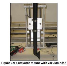
The reason for this is so that when the z-actuator is in the initial top position, the hose tip
will be at the sand surface. Thus, the vacuum hose will be able to reach any desired depth in the
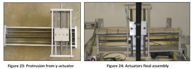
box. A single piece of aluminum that is 4 ½” in length has been mounted horizontally to the face
of the y-actuator mounting plate and two more pieces of aluminum that are 2” in length are
mounted to the sides using ¼-20 screws. Shown in Figure 23 is the protrusion from the yactuator
mounting plate to provide the z-actuator with clearance spacing. Figure 24 shows a
final assembly of the y and z actuators.
In order to keep sand and other materials out of the wheel tracks and the actuators due to an
outdoor environment, two different methods are applied. First, to keep sand from getting into
contact with the lead screws of the y and z actuators, plastic accordion style rod boots, may be
used. They can be mounted to each side of the lead screw nut assembly and attached to the
outer walls of the actuators. As the actuators move in either direction, the rod boots will extend
or retract based on the direction of motion. Second, the bearings chosen for the eight foot
stabilizer bars can also have shields and brushes that will knock off any debris before it can get
caught up in the bearing.
Figure 23: Protrusion from y-actuator Figure 24: Actuators final assembly 18
As far as using different materials in our design, such as aluminum structures, steel threaded
rod, and bronze nuts for the threaded rod, corrosion should not be major factor. When using
the bronze nuts for the steel threaded rod, McMaster Carr’s website states that bronze has a
very high copper content which makes it more corrosion resistant that brass, and will not have a
problem when used with the steel threaded rod. The ACME threaded rod is made of hardened
304 stainless steel which is very highly corrosion and rust resistant. Because of the material of
the threaded rod, it will not corrode or produce rust when in contact with the aluminum
structures. As far as the aluminum frame rusting or corroding, this is not a problem due to the
fact that the apparatus will only be used for a period of four to eight hours in an outdoor
environment. The experiment, run by Eglin, is only done about once every month to month and
a half, and when it is not in use it is stored in an indoor environment.
|