
Battery powered cars are growing in demand, increasing the use and safety concern of high powered lithium ion batteries. Hybrid vehicles are powered through both traditional engines and battery packs, reducing the overall fuel usage. As a result, the batteries produce excess heat while powering the vehicle. Without proper cooling, the batteries risk thermal runaway. This is where the temperature increase causes destructive results, such as fires or explosions. Thus, safety is important motive for our project.
The goal of this project is to improve the structural and thermal management of a hybrid car battery, thus maximizing the safety for the user and efficiency of the vehicle. The structural side of the project focuses on protecting the battery from impacts. The thermal side of the project focuses on cooling the battery using extended fins. These are used along with other design considerations, such as component placement and material selection. The battery system is designed and tested to ensure the safety of the user. Overall, this aids in the advancement and safety of vehicle batteries.
The primary goal for this project to design, test, and build a structurally and thermally advanced battery casing for an SAE Formula Hybrid vehicle. The battery structure will withstand the dynamic loads associated with high speed turns, impacts, and vibrations. There will be a thermal management system integrated with the battery pack to maintain the required operating temperature range. Structural and thermal analysis will be carried out using Finite Element Method. Testing methods will be chosen based on availability and relation to vehicle simulations.
| Team 508 Questions | Customer Statement | Interpreted Need |
|---|---|---|
| Will a vehicle be provided or is there an existing/theoretical vehicle that we are implementing the battery into? | You can use your student chapter of SAE’s vehicle. | Design battery housing dimensions for application in the existing FAMU-FSU SAE vehicle. |
| Where will our battery be tested and applied? | Act as though the battery will be used in the SAE Formula Hybrid competition, in New Hampshire. | Base thermal constraints off of ambient temperatures in New Hampshire in April. |
| Will we need to consider a charging unit within the battery? | It’s up to you, but charging has extra thermal considerations. | The battery dissipates excess thermal load from charging. |
| Last year’s senior design has a 4 cell module in the battery pack, will we need more? | Yes, and race power requirements will help decide how many. | The battery pack provides adequate power for race requirements, while conforming to SAE Formula Hybrid race specifications. |
| What kind of force does the battery pack need to withstand? | The car will experience G-force in turns and acceleration as well as impacts and vibration. | The battery pack safely withstands impacts from all directions and structural vibration from driving. |
Through various concept selection techniques, the prioritization of designs based on engineering characteristics was developed. The House of Quality produced a ranking of the importance of each engineering characteristic, through the use of our customer needs. Next, Pugh charts were developed to analyze the best concept in comparison to each other as well as an existing technology. Last, the AHP was used to ensure unbiased decision making in selecting concepts that adhere to each engineering characteristic. Ultimately, the concept that was selected as result of these methods is Passive Air Cooling. Passive Air Cooling is awarded as the final concept for selection, as it adheres to the highest priority customer needs safety and heat dissipation established in the House of Quality and provides superior engineering characteristics than the other concepts compared in the Pugh charts. From here, a detailed design process for this concept is carried out.
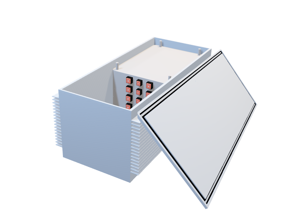
A CAD model of the final design of the battery box is shown below. The front and back walls are made out of Aluminum 6061 that is 3/16 inch thick. The side walls are made out of Aluminum 6061 fins. The six modules are on the inside compressed together by a plate on the top with screws in the four corners. Between the walls and the modules there is thermal pads to better transfer the heat from the modules to the fins. The modules are seperated by an insulative wall with the BMS and electrical components being on the other side. Full specifications and design aspects can be found in the operation manual in the documents section.
Project Charter Customer Needs Functional Decomposition Targets and Metrics
VDR1 Concept Generation Concept Selection Bill of Materials
VDR2 Spring Project Plan VDR4 VDR5 Operations Manual
To test and validate our design the team will do tests that match SAE requirements as well as general safety precautions.