To increase fuel economy, many automotive companies plan to put hybrid drivetrains into class eight trucks. While speeding up, hybrids use an electric battery for power. During steady driving the internal combustion engine delivers the power. Fuel economy increases because the battery pack powers the truck while it gets up to speed. Battery cooling must improve to handle the increased heat that larger batteries will produce. A battery can experience damage or catch on fire if it does not receive proper cooling. Proper battery cooling improves the safety and performance of hybrid trucks. Our objective was to increase cooling in a hybrid battery pack to handle higher heat loads.
Our design uses liquid cooling within the battery modules. The design uses coolant channels routed through aluminum cooling plates. Coolant pumped through the channels absorbs the heat from the plates. This will pull heat away from the battery's cells, keeping the cells at a safe temperature. The design uses large surface contact between the battery’s cells and the cooling plates to increase the heat transfer. The coolant channels limit the pumping power needed by covering only the hottest section of the cell. The team created a computer model to simulate the design. Testing performed on a physical model of the cooling plates determined the heat the design could remove from the pack. Comparing the physical test results to the simulation further confirmed the design.
Using liquid cooling within the battery pack removes more heat compared with other cooling methods. This allows the battery to handle harsher driving conditions without the risk of overheating. Our design achieves increased cooling through liquid cooling in cold plates placed directly within the battery modules. This ensures the battery stays cool and increases the overall performance of the battery pack.
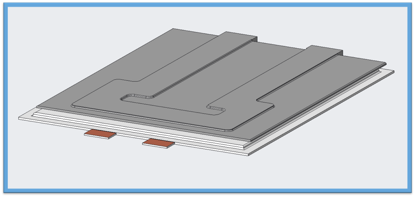
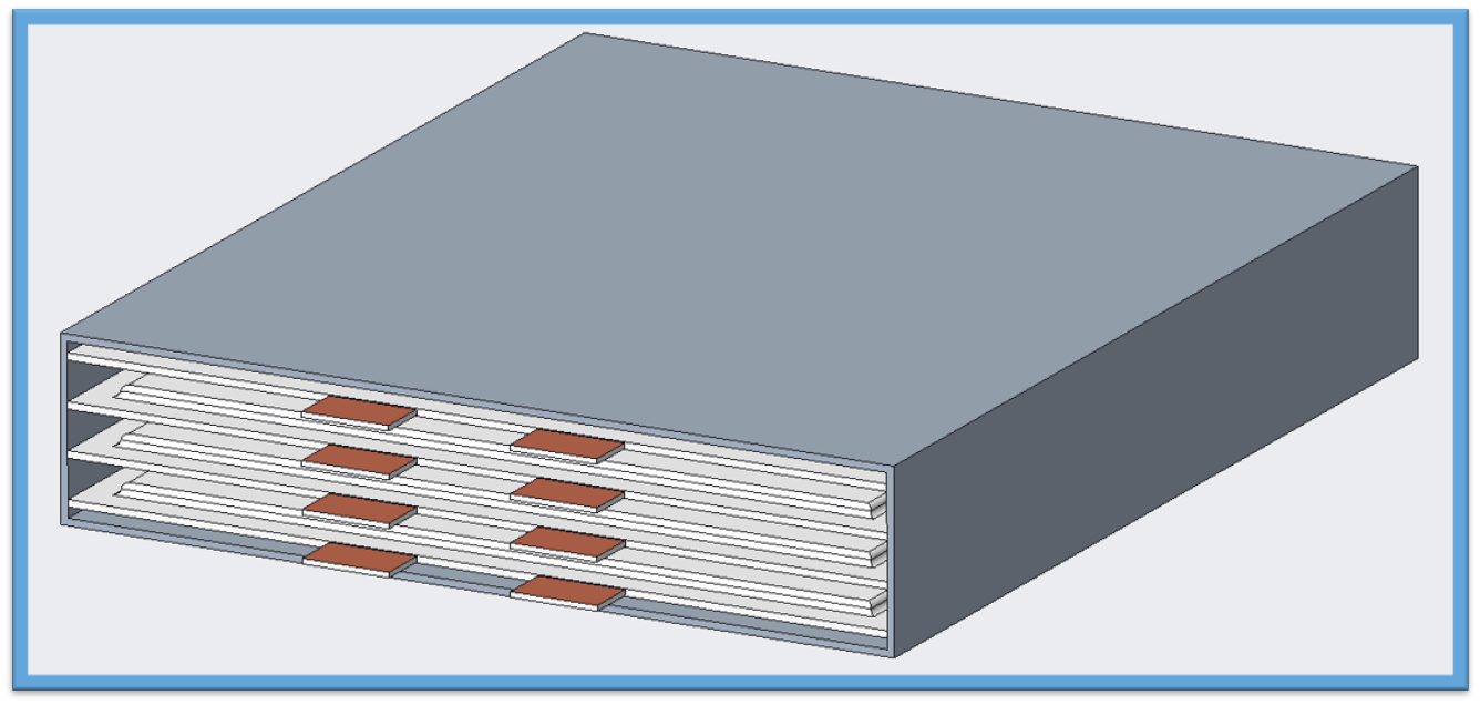
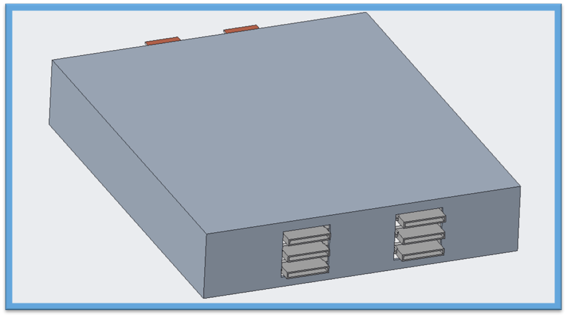
The team chose to implement a liquid cooling system within the battery modules. The cold plates will be placed between each of the battery cells and coolant will flow through the channel in the plate and remove heat from the battery. The coolant channel has been optimized to increase heat transfer while limiting pumping power required to move coolant throuhgout the plate. The shape of the coolant channels has been optimized to target the hottest areas of the pouch cells. Most of the heat in the pouches radiates from the tabs on spreads out to the sides of the cells. The figures below show the configuration of the design implemented into a module. The cooling plates are placed between each of the cells and the aluminum module encases the components. The coolant channels will connect in the back of the module. The coolant will travel to the front of the cell and collect the heat near the tabs and exit in the back.
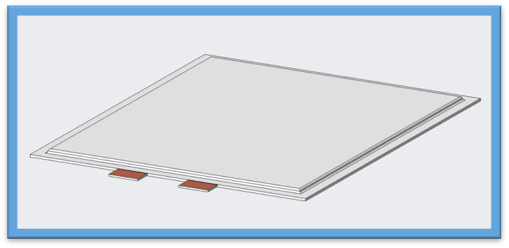
Figure 1: Typical pouch cell.
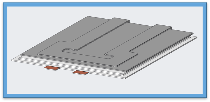
Figure 2: Cold plate design on top of pouch cell.
Figure 3: Stacked layers of cooling plates and pouch cells.
Figure 4: Module design with cooling plates and pouch cells.
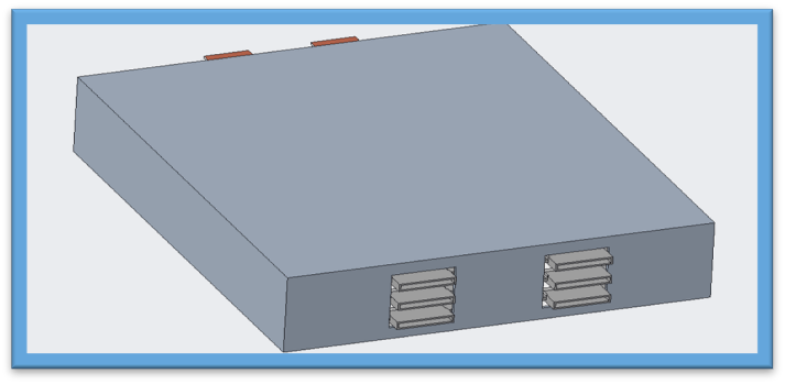
Figure 5: Back view of pouch cell module.
Figure 6: Exploded view of module with inlet and outlet fittings.
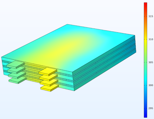
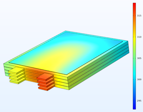
Figure 7 and 8 show a COMSOL CFD simulation of our cooling plate design compared to an industry standard air cooled system. After running the pouch cell at a C-Rate of 5 for 70 seconds the maximum temperature of the pouch using our cooling design reached 308K(35°c). The industry standard air cooled system reached a maximum temperature of 317K(44°c). This shows a 17% increase in the effectivness of our design compared to the industry standard. Our design kept the battery cells 5 degrees under the max operating temperature while the air cooled system went over the max temperature by 4 degrees.
Figure 7: Max temperature of cells using our cooling design.
Figure 8: Max temperature of cells using air cooled industry standard.
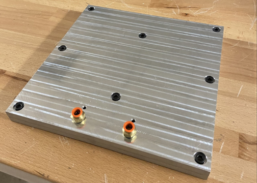
Due to budget constraints the team was not able to manufacture the ideal cold plates that were designed. The ideal cold plates use a manufacturing process called roll bonding where two thin aluminum plates are fused together at high temperature and pressure to form a single plate. A mold is placed between the plates that forms the shape of the coolant channels that will flow through the inside of the plate. Our team came up with a prototype design shown in Figure 10 which resembles the ideal plates but are thicker and use a gasket to seal two individual plates together. Figure 9 shows the module setup that we used for testing. The module includes two cold plates, four heating pads used to simulate pouch cells, a wooden box to represent the module walls, and a pump to pump coolant through the system. Thermocouples were screwed into the cold plates to measure the inlet and oulet temperature of the coolant to see how much heat the plates were removing from the heating pads.
Figure 9: Prototype module used for testing.
Figure 10: Prototype plate used for testing.

Manufacturing Engineer
Chris will graduate with a Bachelor of Science in Mechanical Engineering from the FAMU-FSU College of Engineering through Florida State University in Spring 2023 and continue his education to obtain a Master of Science in Mechanical Engineering beginning in Fall 2023. He is on the dynamics track, with hopes of pursuing a career in a motor sports related field.

Design Engineer
Clayton will graduate with a Bachelor of Science in Mechanical Engineering from the FAMU-FSU College of Engineering through Florida State University in Spring 2023 and continue his education to obtain a Master of Science in Mechanical Engineering beginning in Fall 2023. He is on the dynamics track, with hopes of pursuing a career in the automotive industry.

Systems Engineer
Corey will graduate with a Bachelor of Science in Mechanical Engineering from the FAMU-FSU College of Engineering through Florida State University in Spring 2023. He is in the aeronautics track and plans on pursuing a career in nuclear research or nuclear power generation.

CFD Engineer
Jacob will graduate with a Bachelor of Science in Mechanical Engineering from the FAMU-FSU College of Engineering through Florida State University in Spring 2023. He is in the materials track. He will persue a career in industry after graduation.

Test Engineer
Anthony will graduate with a Bachelor of Science in Mechanical Engineering from the FAMU-FSU College of Engineering through Florida State University in Spring 2023 and continue his education to obtain a Master of Science in Mechanical Engineering beginning in Fall 2023. He is on the thermal fluids track, with hopes of pursuing a career in fluids.

Cummins Inc.

FAMU-FSU College of Engineering


