Tribometer in Space-like Conditions

Team 501
FAMU-FSU College of Engineering
Department of Mechanical Engineering

About the Project

At the FAMU-FSU College of Engineering's Aero-propulsion, Mechatronics, and Energy Center (AME), we are transforming material testing using a device called a tribometer. This innovative tool is essential for measuring aspects such as the coefficient of friction, the wear rate, the friction force, and the normal force. The coefficient of friction indicates how rough or smooth a surface is. The wear rate is the speed at which a material deteriorates due to friction. The friction force is the resistance generated by two surfaces rubbing against each other. The normal force is the force applied perpendicularly to the material being examined. Our tribometer is designed to replicate space-like conditions. Spacelike conditions means it operates in a vacuum and endures extreme temperatures. Although there are existing tribometers capable of functioning in such harsh environments, they typically face challenges with lengthy setup and takedown times and are limited to testing one sample at a time. In contrast, our tribometer aims to decrease the setup time and has the capability to test multiple samples at the same time. This efficiency is vital in the aerospace and automotive industries, where optimizing time and reducing costs are important. Furthermore, our tribometer's ability to conduct tests under these conditions both accurately and safely is a major mile marker in tribological research. This progress is expected to lead to the development of high-quality aerospace and automotive components. Our research enhances the understanding and performance of materials under extreme conditions and contributes to the innovation and efficiency within the aerospace and automotive industries.

The Design

The Official Approved Design

The intricate network of components within a tribometer assembly orchestrates a symphony of motion and measurement, each element meticulously engineered to fulfill a specific function. Take a look at the key components of the tribometer assembly as well as their roles and interactions in facilitating precise testing and analysis in tribological studies.

  • Motor: The motor used in the system is the combination of Screw Drive GP 16 S Ø16 mm and EC-max 16 Ø16 mm motor. The Screw Drive GP 16 S Ø16 mm is a precision-engineered ball screw system designed for linear motion applications. With a diameter of 16 mm, it provides reliable and efficient movement ensuring smooth and precise translation. The EC-max 16 Ø16 mm motor is a brushless, high-performance electric motor with a power rating of 8 Watts. Being brushless makes it more durable and efficient, as it eliminates the wear and friction associated with traditional brushed motors.

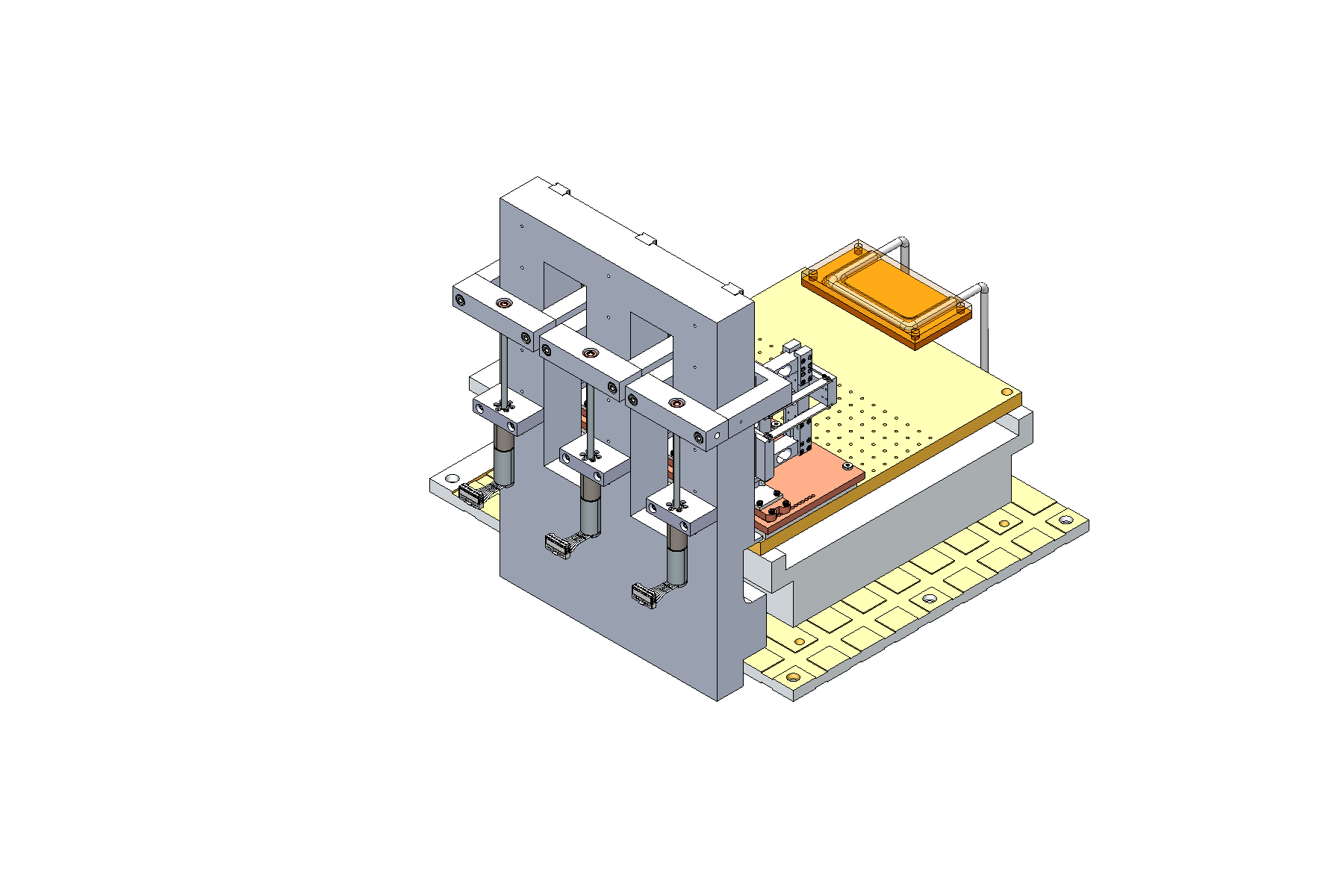
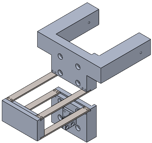
    Motor Mount: The motor mount has two important parts: the motor holder and the nut adaptor. The motor holder puts the motor upside down on the backplate to make things move in a straight line with tension. This helps avoid any looseness in the material when it's rolled or unrolled. The nut adaptor holds the nut that connects to the motor ball screw and links the motor to the rail assembly, making sure the straight-line motion moves smoothly in the whole system. So, the motor holder and nut adaptor work together to keep everything running well and prevent any unwanted slack in the material.

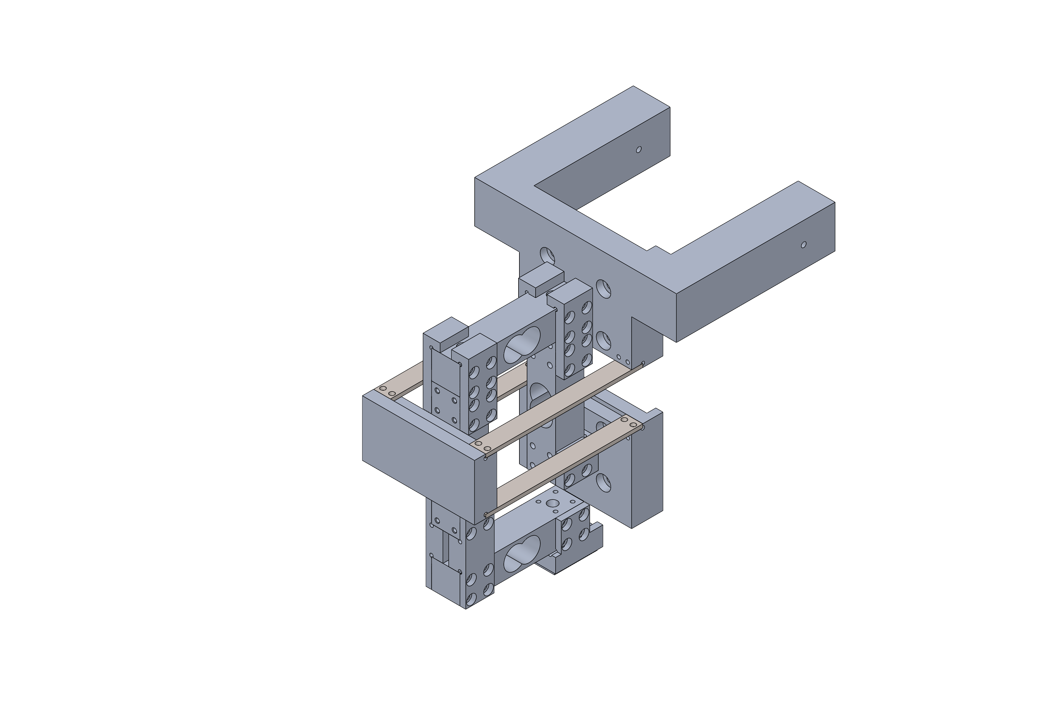
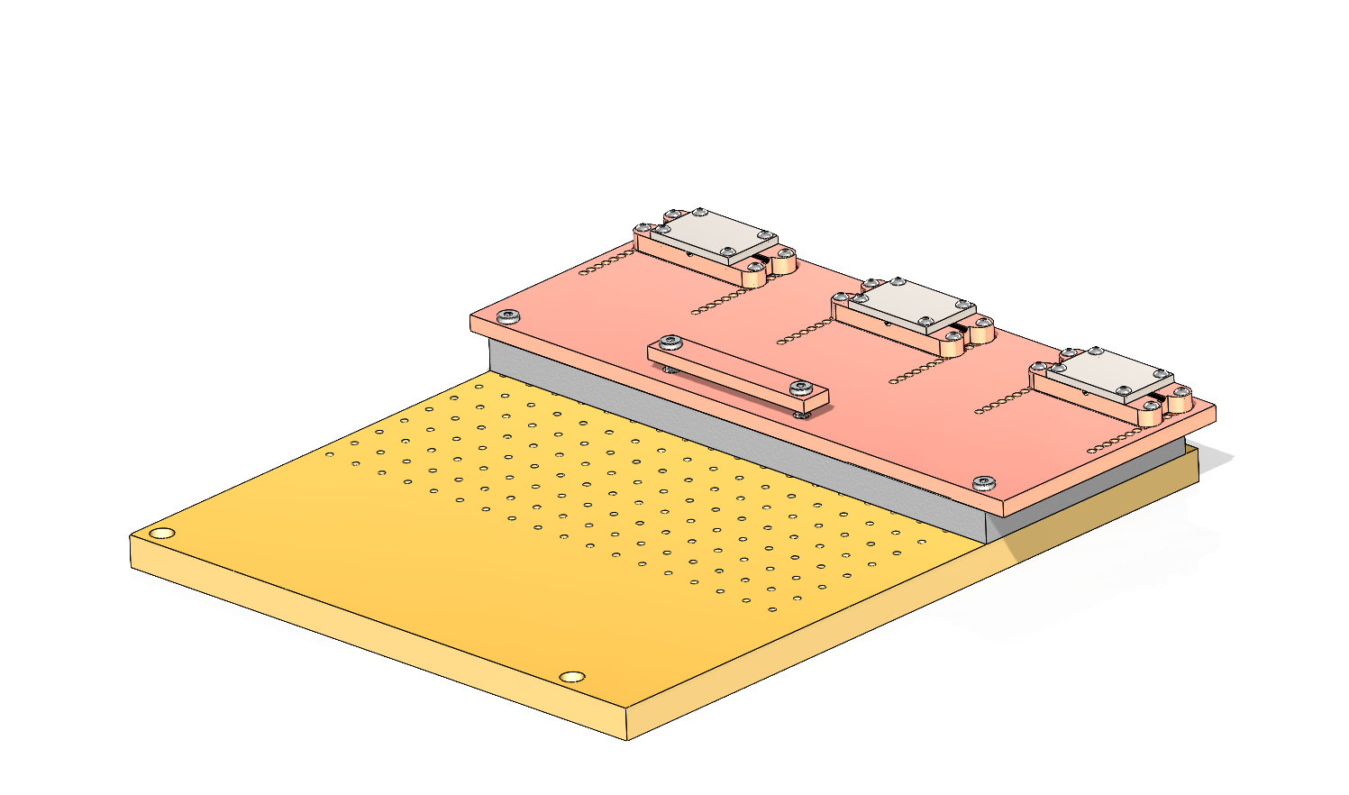
    Minirail Linear Actuator: The minirail plays a pivotal role in transmitting precise linear motion to the Tribometer Head. It operates with a motor, which initiates a circular motion. This circular motion undergoes a transformation into a straight-line motion through a threaded mechanism within the nut adaptor, and the nut adaptor is connected to a cart that drives along a rail to move the head in the z-direction. In essence, as the motor generates rotational force, the minirail, threaded mechanism, nut adaptor, cart, and rail collectively collaborate to ensure the smooth conversion and transmission of motion. This integrated system not only facilitates the practical application of linear motion to the Tribometer Head but also underscores the significance of each component's contribution in achieving a well-coordinated and efficient operation for precise testing and analysis in tribological studies.

  • Leaf Spring: The leaf spring in our tribometer assembly is engineered to achieve a minimum deflection threshold of 4mm. Its primary role is to effectively mitigate any deflection experienced by the tribometer head assembly. This critical function ensures that our test sample maintains a precise perpendicular alignment relative to the counter sample. As a result, the sample consistently interacts with the entire cross-sectional area of the sliding surface, optimizing the accuracy of our tribological measurements.

    Load Cell: Our assembly incorporates 20 kg load cells, meticulously selected to measure both normal and frictional forces with high precision. The horizontally positioned load cells are dedicated to assessing the normal load, while the vertically aligned ones are tasked with evaluating frictional forces. Interestingly, our setup includes duplicate load cells for each force type. This redundancy is intentional, providing us with the flexibility to identify the most effective load cell for each measurement through comparative analysis. Finite Element Analysis (FEA) has guided our choice, indicating that the topmost load cell for normal forces and the friction force load cell nearest to the leaf spring are superior in data accuracy. This insight is pivotal for enhancing the reliability of our force measurements.

    Configuration: The slider component of our high cyclic life tribometer is designed to withstand a maximum moment of 18 Nm, necessitating a design that minimizes mechanical stress. By strategically positioning the load cells adjacent to the leaf spring, we've achieved a configuration where the induced moment on the slider is kept below 1 Nm. This optimization was achieved by calculating the product of force and the distance from the sample to the slider, ensuring the moment remains within safe limits. Comprehensive FEA has confirmed that our design effectively eliminates any potential deflection along the x, y, and z axes, thereby preventing interference with adjacent components. This validation underscores the precision and reliability of our tribometer assembly in conducting high-fidelity tribological research.

  • Counter Sample Assembly: The counter sample assembly will consist of five different items connected to the translating stage within the vacuum chamber. The first item is an insulating plate to keep the extreme ranges of temperatures from reaching the translating stage. We chose Polyetheretherketone, or PEEK which is a thermoplastic polymer, for its high melting temperature, thermal insulating capabilities and resistance to wear and fatigue. Next is the copper plate connected to the cooling system. Copper is a readily available material that is known for its thermal conduction. On top of the copper plate are 3 evenly spaced Minco heaters described above, one for each tribometer head. On top of each Minco heater is a substage identical in cross-sectional area. The substage material was chosen to be copper because it is readily available and a good conductor. The last item is the counter sample. The counter sample will be slightly smaller than the substage and the material will depend on the experiment’s needs.

    Heating System: The heating system consists of 3 Minco Polyimide Thermofoil Heaters. The heaters are 0.3 mm in thickness making them ideal to fit in between the copper plate and copper substage. They are rated to operate in temperatures from -200 – 200 Celsius, which is the minimum and maximum temperature range the tribometer will operate in. Each Minco heater can produce a maximum of 166.5 Watts of power, which through heat flow analysis, will be more than enough power to heat the copper substage and counter sample to 200 Celsius.

    Cooling System: The cooling system consists of piping and a copper block. Two holes are drilled into the copper block and connected by braids to holes in the copper plate in the counter sample assembly. Liquid nitrogen will be pumped into the piping, cooling the block and ultimately the counter sample assembly as well. Liquid nitrogen has a temperature of about -190 Celsius.

Load Head Assembly Test

This experiment employed a hand crank stage to maneuver a 440C stainless steel countersample against a PTFE sample. The load cells generated voltage readings corresponding to both frictional and normal forces. These readings were analyzed to determine the coefficient of friction, enabling a comparison with the established coefficient for PTFE. This process served to validate the design effectively.

From these friction force graphs we see a steady increase in voltage around 0.06V and a zero line that stays constant around 0.5425.

The normal force data looks bad due to a lot of noise from not being able to apply a constant force but from these graphs we see a steady decrease in voltage of around 0.6, aligning with our calibration.

After analyzing the friction and normal force data, we plotted the coefficient of friction corresponding to each applied force. By averaging these values, we derived a coefficient of friction of 0.13. This result serves as evidence of the proper functionality of our load head assembly because the established coefficient of friction for a PTFE sample typically falls within the range of 0.1 to 0.2.

Future Work

Timeline of work to complete by the end of the semester:

Integrate Motor Control into MATLAB

Integrate motors into the code for running tests.

Software

Revise and finalize software for the tribometer's functionality and an automated test.

Testing

Submit the final prototype to the automated coefficient of friction test.

Team 501

Madison Retherford

Mechatronics Engineer

Madison will graduate with a bachelors degree in Computer Engineering from the FAMU-FSU College of Engineering. During her studies her interests leaned toward robotics and microprocessor systems which she hopes to pursue a career in after graduation.

Branham Channell

Materials Engineer

Branham will graduate with a bachelors degree in Mechanial Engineering from the FAMU-FSU College of Engineering. His interests include materials, sattelite developement, software developement, in which he plans to pursue a career after graduation.

Cobi Johnson

Systems Engineer

Cobi will graduate with a bachelors degree in Mechanical Engineering from the FAMU-FSU College of Engineering. His interests include material science and engineering design, in which he plans to pursue a career after graduating.

Javier Ibanez

Structural Engineer

Javier will graduate with a bachelors degree in Mechanical Engineering from the FAMU-FSU College of Engineering. His interests include thermo-fluids design and structure design, in which he plans to pursue a career after graduating.

Joshua Wesley

Computer Hardware Engineer

Joshua will graduate with a bachelors degree in Electrical Engineering from the FAMU-FSU College of Engineering. His interests include IC design and hardware design, in which he plans to pursue a career after graduating.

Advisors

Shayne McConomy, Ph.D

Senior Design Professor

Teaching faculty in the Mechanical Engineering Department at the FAMU-FSU College of Engineering

Brandon Krick, Ph.D

Advisor

Associate professor in the Mechanical Engineering Department at the FAMU-FSU College of Engineering Aero-propulsion, Mechatronics, and Energy Center (AME).