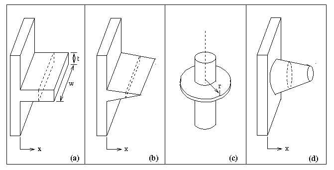
Figure 1. Various extended surfaces
Extended Surface Heat Transfer
|
|
|
|
|
|
|
|
|
|
|
|
To examine the heat transfer in a single cylindrical extended surface (a fin or a pin) in free or forced convection. To develop an understanding of fin effectiveness and the parameters which influence it.
Theoretical Background
( For
more detailed discussion, go to EML
3016 Notes )
An extended surface
is commonly used in reference to a solid that experiences energy transfer
by conduction within its boundaries, as well as energy transfer by convection
between its boundaries and its surroundings. The extended surface is most
often utilized in the removal of heat from a body. In this case, the extended
surface is often referred to as a ``fin''. A fin with a cylindrical shape
and a high aspect ratio (length/diameter) is called a pin. Fins are often
seen in electrical appliance cooling such as in a computer power supply or
substation transformers. Fins are also used for engine cooling. Figure 1
illustrates different fin shapes. The analysis of fin heat

Figure 1. Various extended surfaces
transfer assuming steady
state, one-dimensional heat conduction (temperature varies only axially and
not radially), uniform
convective heat transfer coefficient, h, and constant thermal conductivity, k, results in the differential
heat equation in the following form,
 (1)
(1)
where Ac
is the cross-sectional area, As is the surface area, T is the temperature,
and T¥ is the freestream temperature. If the fin has a
uniform cross-sectional area, Ac, and a base temperature of Tb,
Equation 1 reduces to
 (2)
(2)
where P is the perimeter.
Defining
![]() (3)
(3)
we can rewrite Equation 2 as
 (4)
(4)
where m2 = h P/(k Ac). Equation 4 is a linear, homogeneous, 2nd order, constant coefficient ordinary differential equation, whose solutions depend on the boundary conditions. A summary of various boundary conditions and the resulting solutions are given in Table 1. The effectiveness of an infinite fin is given by
 (5)
(5)
The fin effectiveness is defined as the ratio of the fin heat transfer rate to the heat transfer rate that would exist without the fin. It is often desired to maximize the fin effectiveness. There are various ways to achieve this.
The following apparatus will be used in this experiment:

Figure 2. Cylindrical extended surface, including thermocouple locations
| Case | Tip Condition
|
Temperature Distribution
|
Fin Heat Transfer Rate
|
| A B
C
D |
Convection
Adiabatic
Prescribed Temp.
Infinite fin
|
|

|


|
|||
Table 1. Solutions to fin equation
1. Calculate the non-dimensional temperature
profile
![]()
for each flow situation and compare it to the theoretical temperature profile.
2. Plot the nondimensional experimental and theoretical
temperature profiles on the same graph for
each flow situation.
3. Discuss the results in detail. Compare the experimental
and theoretical values. What boundary
conditions did you assume? Why? What may cause the experimental profile to
differ from the
theoretical profile?
4. Calculate the fin effectiveness. Which case has the highest
effectiveness and why? Discuss ways
to improve fin effectiveness.

Experiment 2 Data Sheet
Note: Please note the units of the quantities which are being measured, when recording data. For example, when measuring voltage, if the voltmeter reads 16 mV, then write down 16 mV instead of just 16.
1. Maintain constant temperature bath at approximately 80 oC.
2. For each measurement allow fin to reach steady state then record the temperature
profile. For
steady state, wait 15 minutes after raising speed in windtunnel.
3. Velocity (m/s)= 0.9523 (counter reading) - 1.4093 (calibration chart)
|
|
|
|
|
|
|
|
|
|
|
|
|
|
|
|
|
|
|
|
|
|
|
|
|
|
|
|
|
|
|
|
|
|
|
|
|
|
|
|
|
|
|
|
|
|
|
|
|
|
|
|
|
|
|
|
-
|
|
|
|
|
|
|
|
|
|
|
|
|
|
|
|
|
|
|
|
|
YOU NEED TO GET THE LAB INSTRUCTOR'S SIGNATURE BEFORE LEAVING.
The student has performed
the experiment satisfactorily and has cleaned the work area.
___________________________ _______________
(Lab assistant's signature) Date