Two teams from Florida State University and the Univeridade Federal do Parana have collaborated together to modify a pre-existing tri-generation system. This system provides electricity, refrigeration, and hot water. A generator is coupled to an internal combustion engine to produce electricity while the exhaust gas from an internal combustion engine is used to provide a cool space and to heat water.
Together the two teams have modified the system in the following ways:
-
 Allowing the engine to operate on compressed natural gas (CNG) and gasoline.
 -
Modifying the refrigeration system so that the temperature is controlled automatically.
-
Modifying the water heating unit so that it can be controlled and fixing a previous overheating issue.
-
Adding a distiller that will provide clean water.


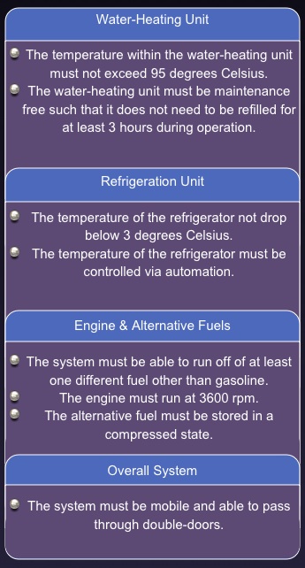
Product Specifications
Concept Generation and Selection
Water-Heating Unit Conceptual Designs
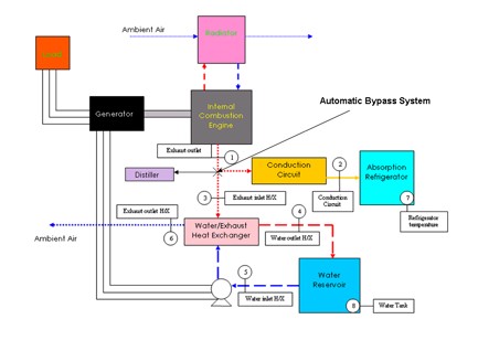
The conceptual designs for the water-heating unit were created in order to eliminate the problem of the water-heating unit reaching temperatures that were damaging to the system. The first conceptual design involved creating an automatic bypass system that would control the heat flow to the conduction circuit and to the water-heating unit. This concept also involves adding a water distiller to the system. A schematic of this concept is shown below in Figure 1. The disadvantage to this concept is that there would not be control over the individual subcomponents (e.g. the conduction circuit and the water-heating unit) of the system.
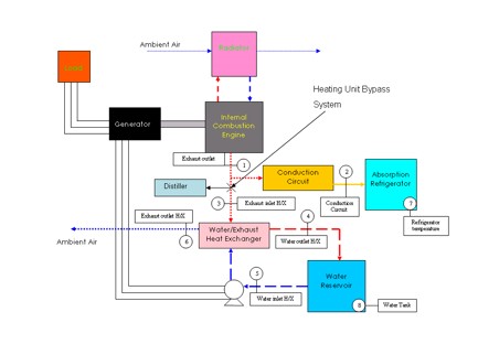
The second concept for the water-heating unit included a bypass system that diverted heat from the exhaust to a water distiller. This design uses an “on-demand” approach where the water in the water-heating unit would only be heated when the user desired hot water. When the user was not in need of hot water, the exhaust gas would then be used to run a water distiller. This prevents the problem of over-heating since when the user needs the water, the hot water is used rather than continuously being circulated and reheated. This concept also has an advantage over the first concept since it allows control over individual subcomponents. A schematic of the second concept is shown below in Figure 2.
Figure 1: Water-heating Unit Conceptual Design 1
 The third concept that was briefly explored took into account making the water tank larger. A schematic of this concept is shown below in Figure 3. By increasing the mass of the water, the water’s thermal energy capacity would be increased allowing the water to absorb more energy without such a large temperature increase. The problem with this concept was that the water tank would have to be increased to such a size that the tank would no longer be able to stay on the cart which would not fulfill the mobility requirement for the entire system.
 In order to decide which design would be best for the water-heating unit, a decision matrix was used to evaluate each concept. From the decision matrix shown in Figure 4, it can be seen that the conceptual design for the heating unit bypass was chosen as the optimal design.
Refrigeration Unit Conceptual Designs
The conceptual designs for the refrigeration unit were based on controlling the heat flow to the absorption refrigerator. The heat flow needed to be controlled in order to prevent the temperature from dropping to temperatures that were too low.
The first conceptual design for the refrigeration unit was to introduce an automatic bypass system. This bypass system would be controlle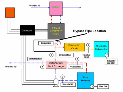 d by an actuator. When the desired temperature of the refrigerator is reached, a signal is created and the actuator would control a valve that would divert the exhaust flow. A schematic of this conceptual design can be seen in Figure 5.
d by an actuator. When the desired temperature of the refrigerator is reached, a signal is created and the actuator would control a valve that would divert the exhaust flow. A schematic of this conceptual design can be seen in Figure 5. The second conceptual design that was explored for the refrigeration unit was introducing a physical separation in the conduction circuit. This break would occur by an actuator when a signal based on the temperature within the refrigerator. When this break occurred no heat will be conducted from the exhaust gas to the refrigerator. The schematic for this concept is shown in Figure 6.
Based on the criteria involved for the refrigeration unit, a decision matrix was formulated and is depicted below in Figure 7. It can be seen that the first conceptual design of adding a bypass pipe was the design that proved to be most feasible.
Figure 2: Water-heating Unit Conceptual Design 2
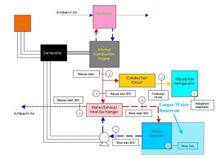
Figure 3: Water-heating Unit Conceptual Design 3.
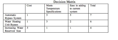
Figure 4: Decision Matrix for Water-heating Unit

Decision Matrices:
Each concept was ranked by how well it met the criteria on a scale from 0 to 3. Where 3 means it meets the criteria to a great extent, 2 to some extent, 1 to a slight extent and 0 means no extent. .
All of the criteria in the decision matrices were considered of equal weight.
Figure 5: Refrigeration Unit Conceptual Design 1
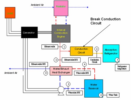
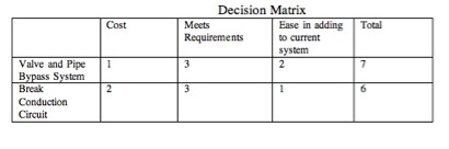
Figure 6: Refrigeration Unit Conceptual Design 2
Figure 7: Refrigeration Unit Decision Matrix
Engine Modification Conceptual Designs
One of the tasks that the group was faced with was to allow the engine to be able run off at least one other fuel other than gasoline. Which alternative fuels would be used and how the engine would be converted was up to the group. Ethanol, hydrogen, natural gas and propane were the alternative fuels that were explored.
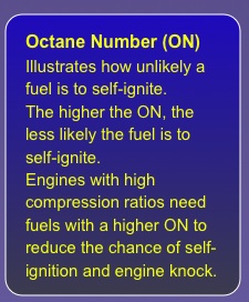
Ethanol was the first fuel to be explored. Ethanol is made from fermented grains and sugar or from ethylene. It was the only non-gaseous fuel to be considered. Ethanol’s physical characteristics are closest to gasoline and is used in many countries as the alternative fuel of choice. Ethanol also is attractive by having less hydrocarbon (HC) emissions that gasoline does. Ethanol also has a higher
octane number (ON) of 118, compared to 87 of gasoline. There are two major disadvantages of using ethanol. The first is that it has a lower energy content than gasoline (about 30% less energy per unit
volume. The second disadvantage of ethanol is cost. The cost of ethanol is great in the United States because of the processing and manufacturing required.
Hydrogen was the second fuel to be explored. Hydrogen as been a popular fuel for some time. There are many advantages of using hydrogen as an alternative fuel. It has no HC, carbon monoxide (CO) or carbon dioxide (CO2) emissions. It also has a high octane number of 130. One of the major disadvantages of using hydrogen as an alternative fuel is fuel storage. For the purposes of this project, hydrogen would be used in its gaseous state, requiring large cumbersome tanks. This would not satisfy our specification of having the entire system be able to fit in a cart that could move through double doors.
Compressed natural gas (CNG) was the third fuel pondered for the project. CNG is made from compressed methane. CNG offers many advantages. CNG is considered to be an environmentally “clean” alternative to petroleum-based fuels. It emissions have less aldehydes and CO2. It also has an octane rating of 130. There are also some disadvantages to using CNG. The first is storage. CNG is stored in a relatively large fuel tank. The second is the safety concerns with the large pressurized fuel tank.
The fourth fuel that was explored was propane. Propane has an octane number of about 104 and it has a high energy content. The emissions of propane are less than gasoline with less nitrous oxide (NOx), CO, and HC. Propane is also an attractive choice since it is most readily available.
As each fuel was looked at, the most attractive fuels were the gaseous ones which are hydrogen, CNG and propane. All of these fuels can be used on the engine with a conversion kit. For gaseous fuels, there are three main conversion methods: spud in, adapter and carburetor replacement. A depiction of the conversion methods is shown below in Figure 7. The spud in method is the cheapest, but is installation can be tricky - the carburetor must be modified by drilling a hole in it thus no longer allowing the use of gasoline.
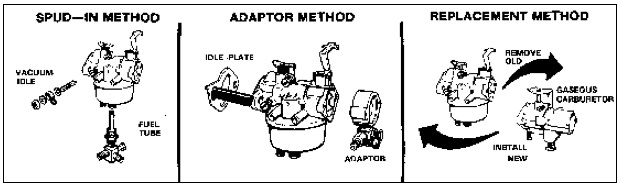 This makes the spud in method an unattractive choice. The adapter method involves installing an adapter between the carburetor and air cleaner allowing for dual-fuel operation. The carburetor replacement method replaces the gasoline carburetor with a new carburetor but does not allow the option of using gasoline. Looking at all of the methods and examining the initial requirements, the the adapter method is shown to be the best method of converting the engine.
After the conversion method was determined, the alternative fuel was selected. Below in Figure 8, the decision matrix is shown. It can be seen that propane was decided to be the fuel to be most feasible when choosing another fuel for the engine to run on.
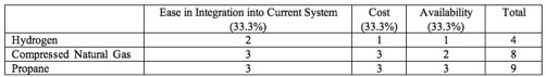
Figure 7: Depiction of Engine Conversion Methods
Figure 8: Alternative Fuel Decision Matrix