|
 |
Team CERN
Collaboration
with Romania
|
The D3 Balance Detection Machine
design has evolved into the form shown in Figure below.
It remains largely the same as the original D3 Balance
Detection Machine concept, however, several
modifications have been made in its development. 80/20
extruded stock is used throughout the assembly as a
framing system, with components bolting onto the frame
using L-brackets (not pictured). The machine may be
bolted down to a table for stability while in use.
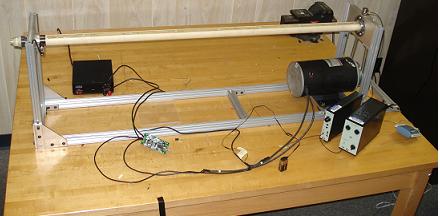
Figure – Balance Detection Machine, pictured with 1.2m
long shaft segment
Regarding the left side of the
machine (see Figure below), the mounting block provides
support for sensor positioning and bearing housing. The
rotary sensor (an optical encoder) provides data for
rpm. The accelerometer (not shown, mounting hole shown
on top surface of plate) detects radial acceleration,
which will be used to derive radial displacement, of the
shaft under rotation. Both sensors are bolted to
brackets connected to the mounting block.
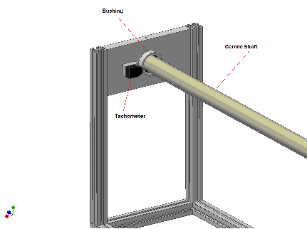
Figure – Left side of the D3 Balance
Detection Machine
The center of the mounting block
has a bushing to allow for the ball bearing to fit
inside it (see Figure below). The flange and bearing
(parts (a) and (h) from Figure of the side view of
ceramic shaft ) will remain connected to the ceramic
shaft and used to mount the segment on the machine. For
shorter length shafts, the motor and bearing-plate
subassembly may be translated down and marked on the
base frame for consistent repositioning in the future.
The left side of the machine will remain fixed, making
calibrations for both configurations easier.
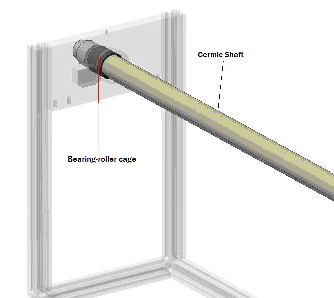
Figure – See-through view of left side of Balance
Detection Machine
Regarding the right side of the
machine (see Figure below), the bearing-plate houses the
open-race bearing and provides a mounting surface for
the accelerometer. The open-race bearing is press-fit
in the plate, and the sensor is screwed into the top
surface of the plate. A split-collar is positioned over
the shaft, slid into the bearing, and is used as a
pulley, ultimately connecting to the motor. The motor
itself will be regulated by a motor controller, which
has a live readout on the Lab View program developed by
the Romanian team.
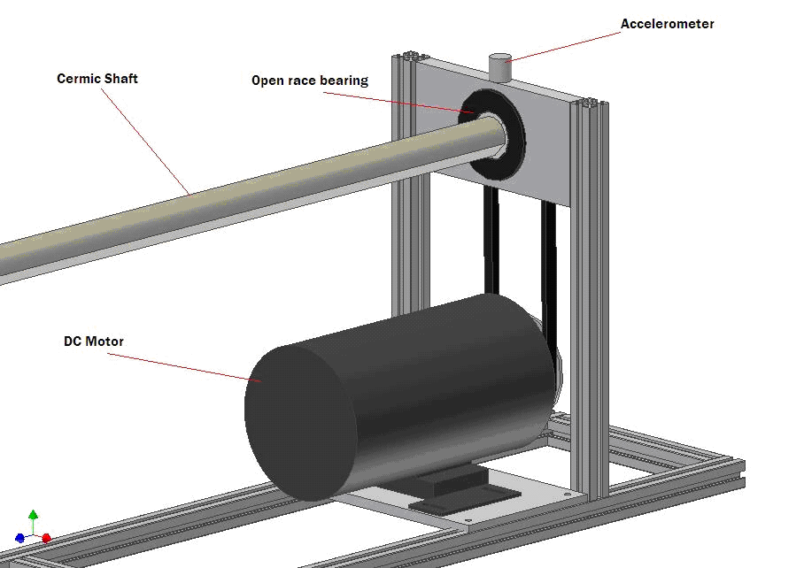
figure – Right side of Balance Detection Machine
The split collar (which also acts
as a pulley) connects to the motor by a pulley system
(shown in Figure below). Pulleys are mounted on the
motor drive-shaft and the ceramic shaft, transmitting
power from the motor to rotate the shaft segment.
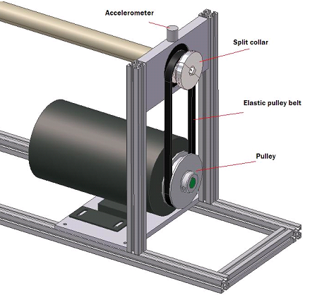
Figure – Right side of Balance Detection Machine showing
pulley system
The following is a description of
the reasoning used to select components used in the
Balance Detection Machine. The Romanian team is
exploring sensor selection at time of writing, hence
only descriptions of required specifications are
included here.
The split collar is one of the
most sophisticated mechanical components of the whole
assembly. It is specifically designed for this
application. The inner surface matches the cross-section
of the shaft. The outer surface is designed to have a
slip fit with the bearing. The split collar is also
machined to act as the pulley that connects the shaft to
the motor. Once attached on the shaft the two halves are
bolted together. The inner surface is also machined to
go around and not touch the inner components of the
shaft.
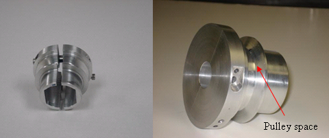
Figure -
Split Collar
The
bearing is an open ball bearing designed for high speed
applications. It has an 85 mm outer diameter and it fits
45 mm diameter shafts. The bearing can handle up to 8800
Maximum RPM. As shown in the picture the bearing was
press-fit into the bearing plate.
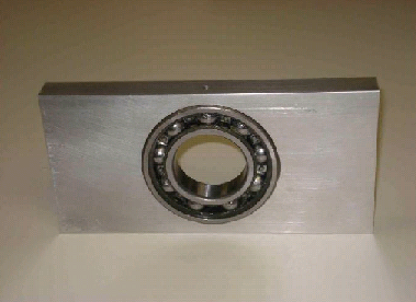
Figure - Bearing Plate
Pulleys
The
pulley that is mounted on the Motor shaft is a standard
V-belt drive Pulley purchased through McMaster-Carr,
with a 10.16 cm outer diameter. The other pulley is
enclosed in the split collar and it has a 6.0 cm outer
diameter. The diameters of both pulleys were
specifically designed to be different so the motor
vibrations can distinguished from the mass imbalances of
the shaft when doing the FFT.
Drive Belt
The belt
is made out of thermo-plastic and it can be welded
together for the desired length. It is 0.95 cm in
diameter and 65.56 cm long.
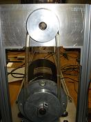
Figure - Pulleys and drive belt
The
supporting frame is relatively simple. It consists of
80/20 railings cut to precision and Aluminum plates that
the shaft and electric motor rest on (see picture). The
frame is assembled together with L and T brackets. Since
most of the material is Aluminum the frame is light
which allows for extra mobility, but it will need to be
bolted down to a much heavier platform so no extra
vibration is induced.
The motor is very robust, total
power being rated up to 1 Hp. At full load it draws up
to 41 Amps of DC current and a potential of 24 Volts.
However it will never reach these specs because it is
limited by the power supply (see below). One of the
advantages of this motor is the weight, being the
heaviest component of the whole assembly, which helps
with damping the system. Also very little vibration
comes from the motor, even when operated at high
frequencies. But to minimize the motor vibration even
more a damping material is places in between the motor
and motor plate. One little disadvantage is that it is a
little noisy when operated at low frequencies.
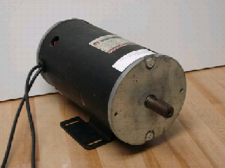
Figure – One horsepower motor
The motor
controller was bought as a kit and put together by
soldering all the components to the PC board. Originally
the controller was rated 12-32 Volts DC at 5 Amps, but
some modifications were made by adding 16 Gauge wire
through to the mosfets channels (see picture). With this
modification the controller can handle motors rated up
to 47 Amps. Motor speed control is done by manually
rotating the potentiometer. Also a nice feature although
not required about this controller is that it allows
bi-directional rotation.
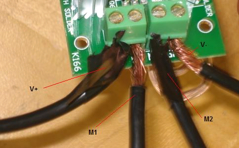
Figure – Motor controller configuration
The motor
power supply was bought directly from
Radioshack
store. It outputs up to 15 Amps at 13.8 Volts DC. The
nice feature about this Power Supply is that it plugs
directly into the wall outlet, eliminating the need of a
battery source. Also the On/Off switch can be used as an
emergency power cutoff.
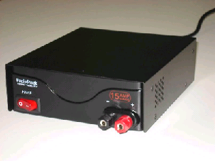
Figure – AC/DC Power supply
*The following electronic
equipment was borrowed from Dr. Patrick Hollis for
running the experiment. Once shipped to CERN, similar
Equipment will be purchased for the machine.
The
accelerometers are Bruel
& Kjaer brand, type 4381. It is a high sensitivity
piezoelectronic charge accelerometer (98 pC/g) that can
be used for low frequency measurements. It is being
powered be the Sensor power Supply that connects through
the Charge Amplifier.
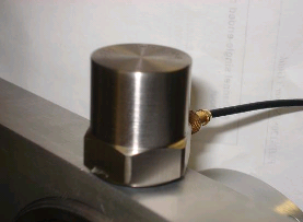
Figure - Accelerometer
The
Photoelectric Tachometer is Bruel & Kjaer brand as well,
Probe MM-0012. It can be powered up by simply connecting
it to a 9 Volts battery. The BNT cable that connects to
the tachometer was modified so it can be connected to
the battery and the DAQ. The tachometer emits a infrared
light that is reflected back by a reflective strip
attached on the shaft. Also the distance between the
tachometer and reflective strip was minimized to about 4
mm for better feedback.
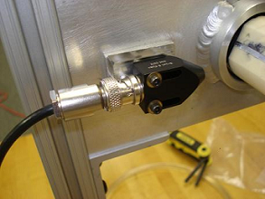
Figure - Tachometer
The
Sensor Amplifier is also Bruel & Kjaer brand, model
2651. It enables a charge amplification of up to 10x.
That way the sensitivity of the accelerometer can be
increased up to 980 pC/g. It also connects the
accelerometers to the DAQ and Sensor Power Supply.
The
sensor power supply powers up the accelerometer and
Charge amplifier, by simply plugging it into the wall.
It caries a Bruel & Kjaer name brand as well.
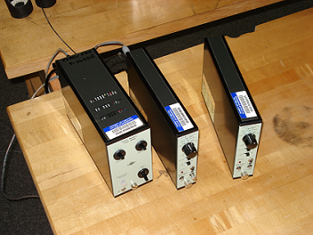
Figure – Power supply and Charged Amplifier
The Data
Acquisition Board (DAQ) transmits the accelerometer
signal to the computer where it can be further analyzed.
It is Computing Measurements brand model USB-1208FS. It
connects to computer through USB cable and has an up to
12 bit resolution. The scan rate is 50,000
scans/second.
80/20 manufactures industrial
erector sets, t-slot extruded stock that may be used for
quick assembly of machinery. The stock is made from
6105-T5 Aluminum, and is readily available through
industrial suppliers such as McMaster-Carr or Reid
Supply. A whole line of accessories are sold for the
stock as well, including T-nuts and L-brackets,
necessary for bolting frame pieces together. At $3.35
per ft from McMaster-Carr, it is ideally suited for this
application.
Copyright
2007 CERN Team USA Group 13 Inc. All rights reserved. |