
The Subscale vehicle was a prototype version of the Fullscale rocket design. It existed to showcase proof-of-concept at a lower cost & risk to the team. Subscale v1 was the first iteration and was made from cardboard, PETG, and some fiberglass, but crashed due to a recovery/material failure. Subscale v2 recieved a construction overhaul using fiberglass components for the airframe, and provided a successful flight
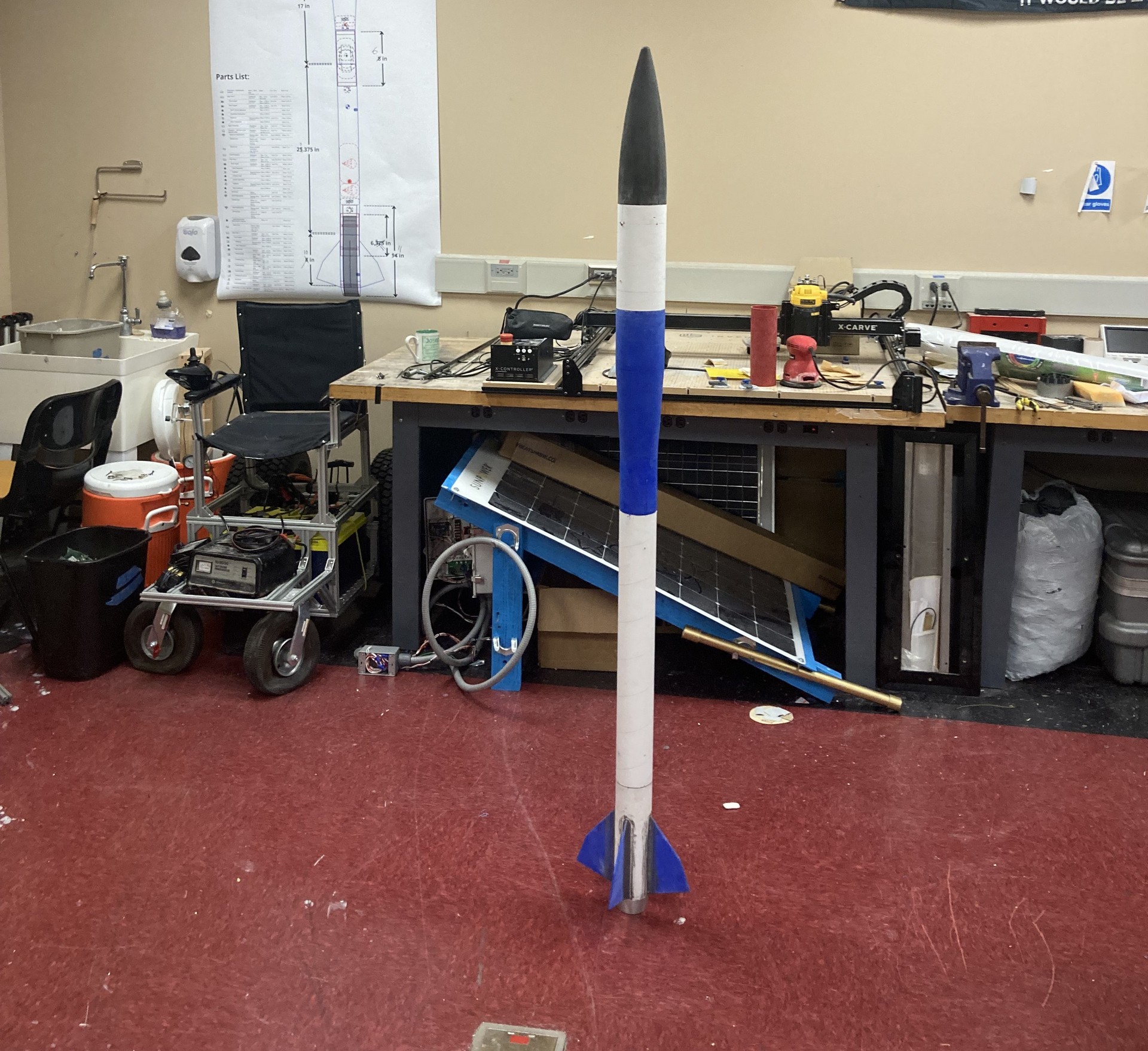
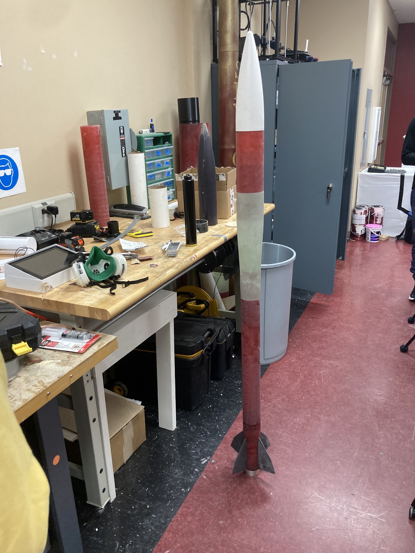
A side-by-side comparison is shown above of the unpainted v1 (left) and v2 (right) subscale rockets. A clear visual difference can be noticed between the weak cardboard airframe of the v1 & the reinforced fiberglass v2 airframe.
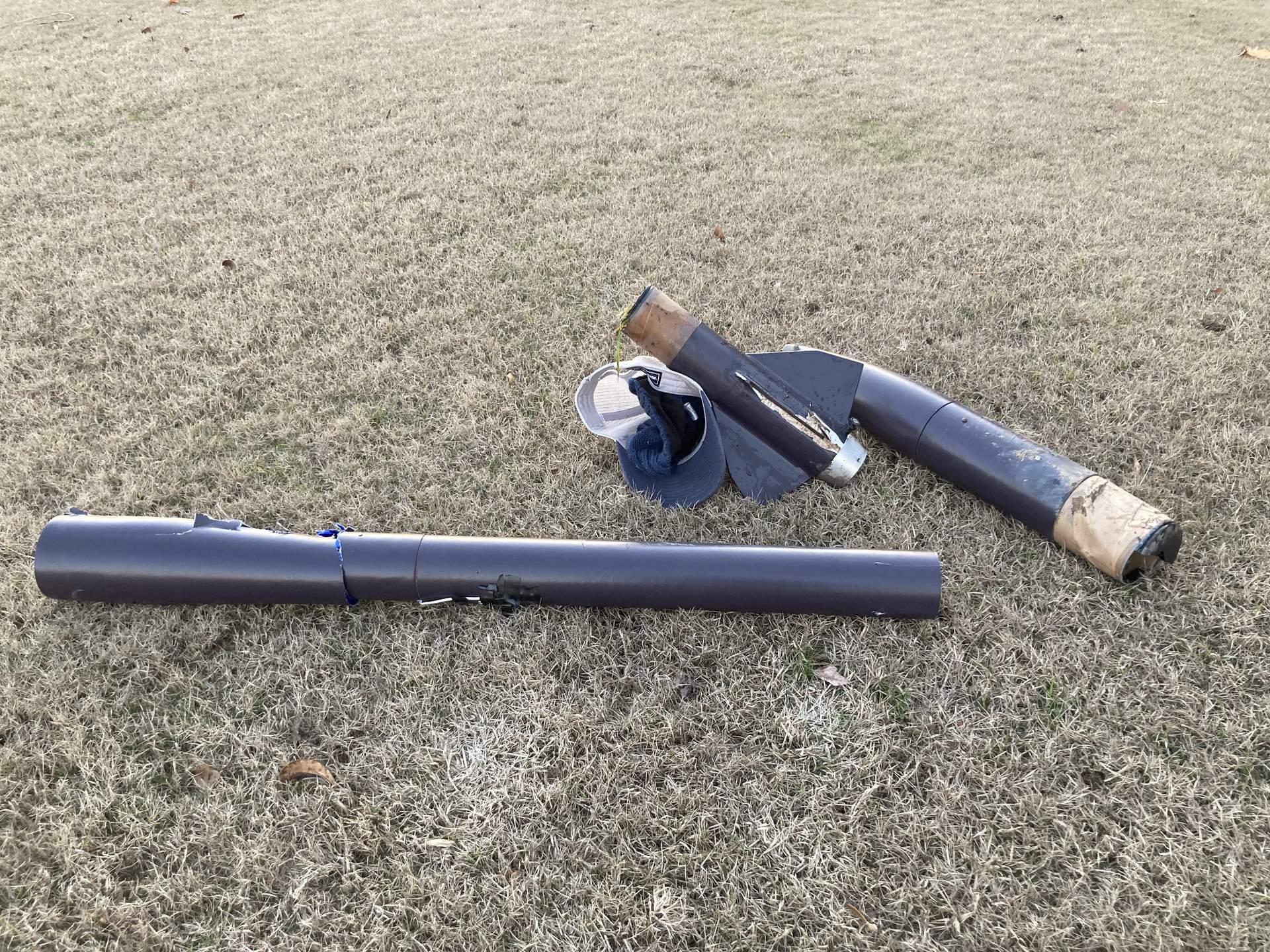
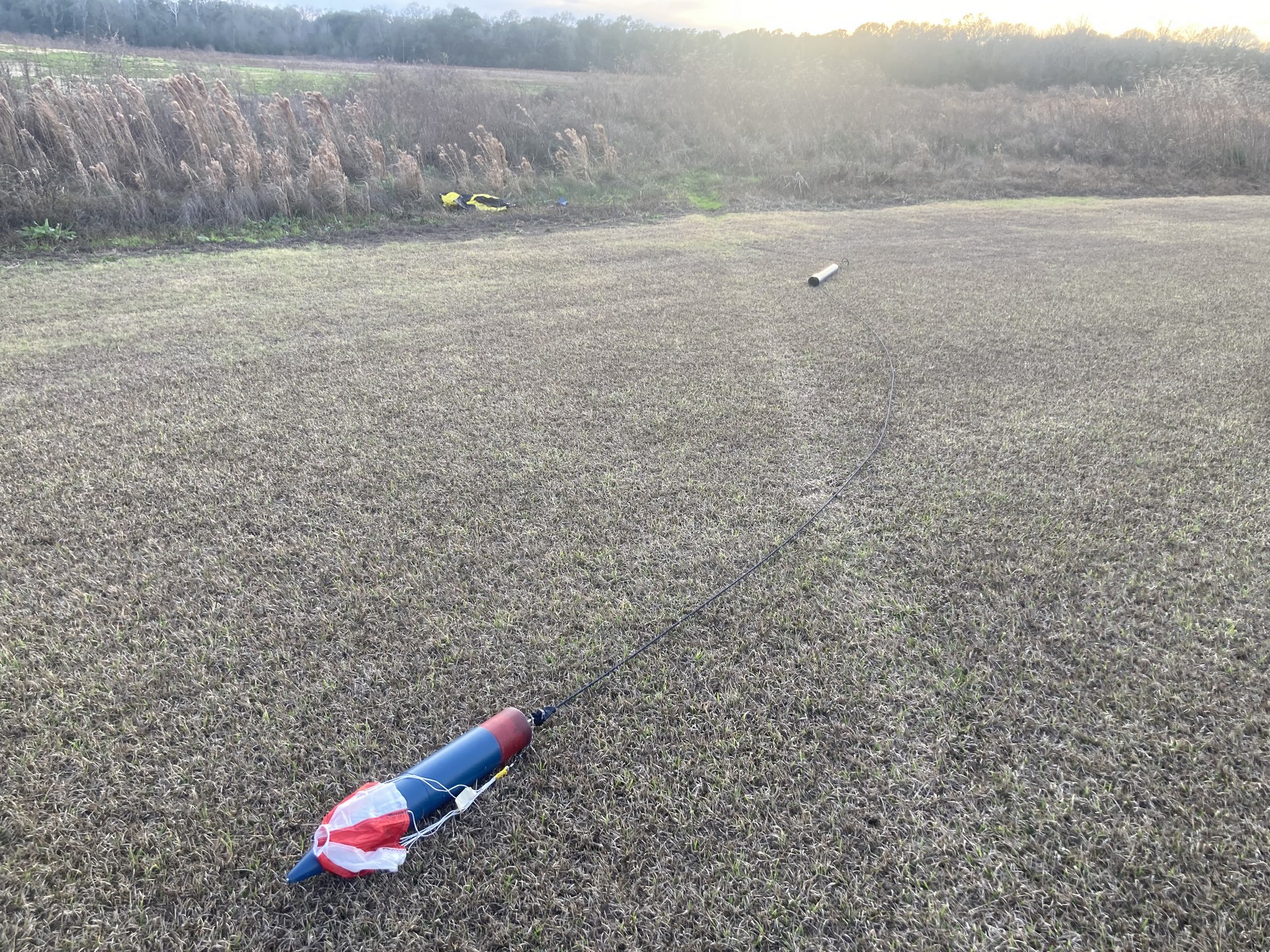
A side-by-side comparison of the v1 (left) and v2 (right) rockets post-landing. The v1 shows significant sights of damage via dents, cracks, and missing parts, while the v2 is in perfect condition - signaling a successful landing.
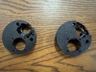
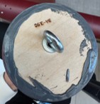
Finally, a side-by-side comparison of the bulkheads used in the v1 (left) and v2 (right) rockets. Bulkheads are used as hardpoints that attach recovery hardware to the vehicle, ensuring all separating sections return to ground as one unit. The v1 used 3D printed PETG as the bulkhead material, which was a factor in the failure of the vehicle recovery as the hardpoints failed decisively. The v2 saw success with a more traditional plywood bulkhead.
The Fullscale Vehicle is acts out the main objectives for this project. This is the vehicle we designed and tested with the subscale, and will accomplish our overall mission at the competition. This vehicle is roughly 10' long with a variable diameter from 6"-5" via a custom made transition. Its mission is to deliver a payload to an altitude between 4000-6000 ft, and land it safely on the ground within 80 seconds of apogee. This section will highlight some key design decisions that make our vehicle unique.


HAUS
AVIONICS
PROPULSION
Shown above is a view of the unpainted fullscale rocket, and a section view (made in OpenRocket). The section view separates the overall vehicle into HAUS, AVIONICS, and PROPULSION sections. The HAUS section holds the payload and its deployment mechanism, the AVIONICS section holds all flight computer systems & recovery equipment, and the PROPULSION section houses the motor.
The mission of the HAUS (Habitat Agricultural Utilization Study) System is to autonomously collect a 50 mL sample of soil and test it for pH within 15 minutes of landing. The Terra Inquisitor resembles a rover in function and is deployed using a mechanical separation system that drives the nosecone of the rocket off using power screws driven by a worm and bevel gear system powered by a DC motor. This system ensures proper deployment orientation using a spring-loaded arm that rotates the rocket HAUS section into the correct orientation. Powered by a custom PCB (printed circuit board) brain, the Terra Inquisitor collects a sample of soil using its unique driving linkage design to orient and power its drilling head system for repeated soil collection. The linkage system also rotates back into the payload chassis to eject the collected soil into its collection and testing chamber. The deposited soil is then saturated with water, tested for pH, and the data stored into its onboard SD card.
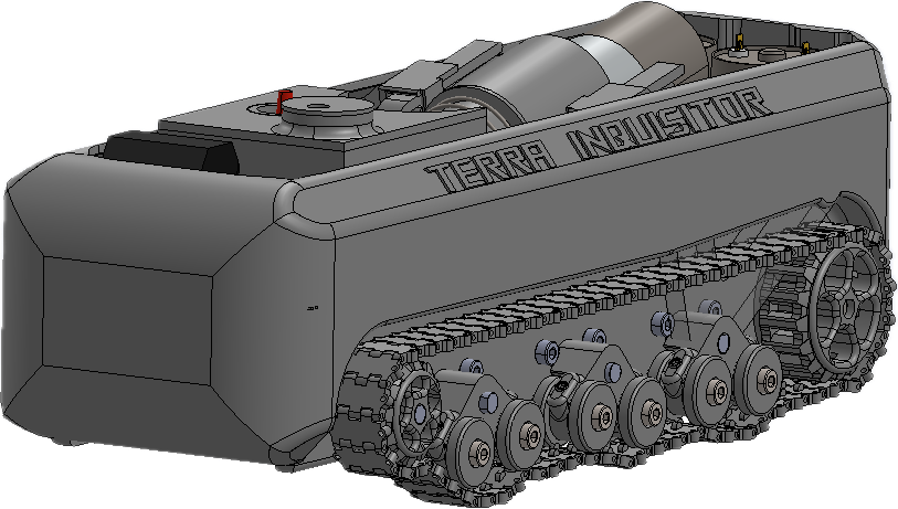
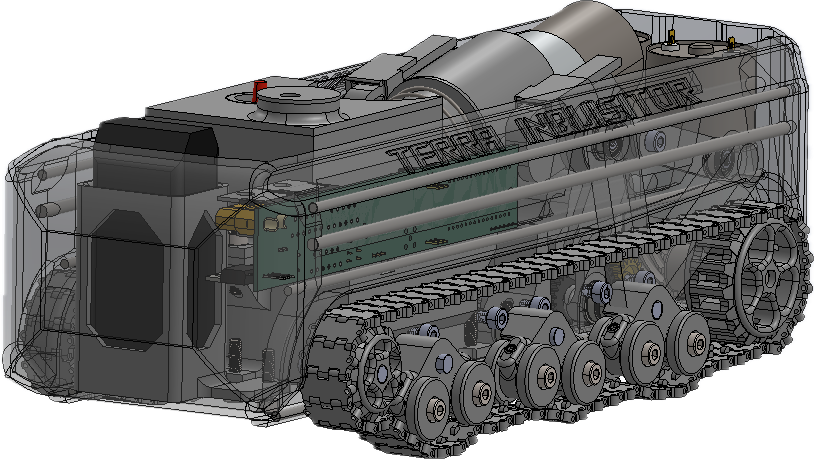
Shown above are solid (left) & holographic (right) views of the Terra Inquisitor payload designed in SOLIDWORKS
The propulsion system involves a dual track system powered at the rear sprockets by two dual Pololu 4742 motors. These motors provide power to the sprockets through their individual crossed helical gear systems that allow the motors to transmit their power from their vertical position to the horizontal 6mm-D shaft attached to the rear driving sprockets. In addition to the powering system, the propulsion system includes the idler rotator wheel assemblies. These assemblies allow the tracks to adapt to the shape of their terrain and thus improve the traction of the system. All rotating components are held in their proper orientation by ball bearings to reduce the overall power loss and the generation of heat and so increase the overall longevity of the design. Combined the 12-volt Pololu motors are able to provide up to 380 oz-in of torque. The Pololu motors were spec’d using a MATLAB simulation designed by the Terra Nova team to optimize the motor selection accounting for different possible orientations of the payload as well as the frictional loss of the tracks.
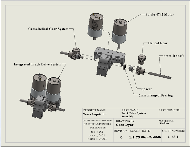
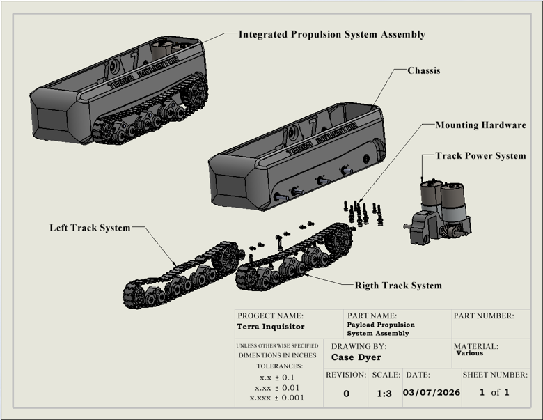
Shown above are drawings of the powerplant (left) & propulsion (right) systems of the Terra Inquisitor designed in SOLIDWORKS.
The most unique feature of the Terra Inquisitor is its implementation of a parallel four-bar linkage system to orient its drilling head system into its vertical drilling position as well as provide assisting ground penetration force. The linkage was designed using the coupler curves, as well as kinematic and kinetic data generated by MATLAB simulations. These coupler curves were then examined for straight line regions that could be used to provide a vertical drilling motion paired with the examination of the average mechanical advantage the linkage system provided during the range of the drilling motion. The selected linkage provided the below coupler curve as well as provided a peak and average mechanical advantage of 66 and 4.4 respectively. The vertical drilling motion this linkage is capable of is 1.3” and providing at least 6 lb drilling penetration force. This system is powered using a servo motor and the power train gear system. (please also see attached videos)
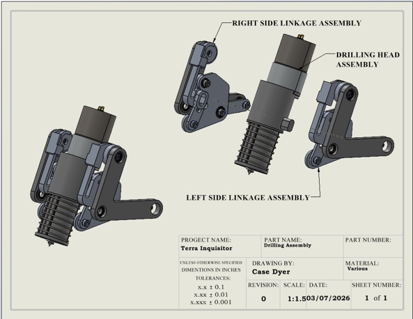
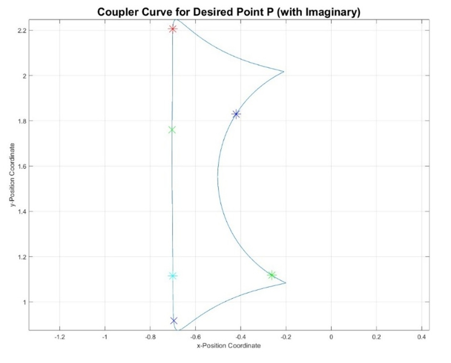
Shown above is a drawing of the linkage assembly (left) and the coupler curve of the drilltip generated in MATLAB
The payload PCB is the custom electronics board at the heart of the Terra Inquisitor, an autonomous rover designed to collect and analyze soil samples after launch as part of a NASA student rocketry competition. The board controls the rover’s various DC motors and reads soil chemistry through a pH sensor, turning a rocket payload into a working field-science instrument. It was designed from scratch using professional circuit-design software and built to be manufactured by an industry PCB fabrication service. The result is a compact, reliable board that brings together motor control, sensing, and power management into a single mission-ready system.
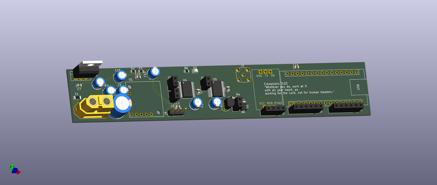
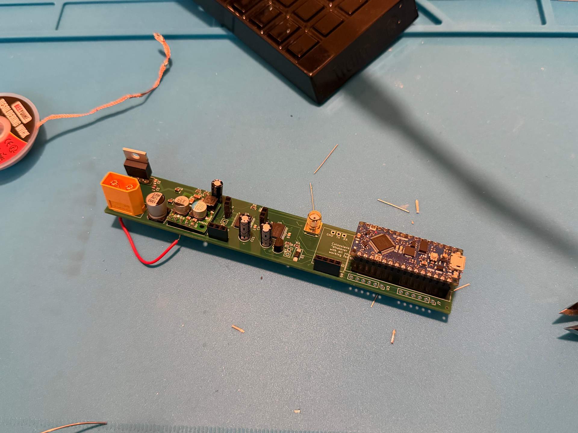
Shown above is a CAD drawing (top), and a photo (bottom) of the custom PCB
The Terra Nova mechanical separation system enables post-landing deployment of the Terra Inquisitor payload without the use of energetics, satisfying NASA HAUS safety and rule requirements. The system is integrated within the forward airframe and employs a 5203 series planetary gear motor, geared lead screws, and a power screw actuation mechanism to generate sufficient force to remove the nose cone and deploy the payload. A power screw architecture was selected because of its self-locking behavior, high force amplification, and inability to lose engagement during operation, providing improved reliability compared to a rack-and-pinion mechanism. Following nose cone removal, a spring-actuated tilting mechanism rotates the payload bay to approximately 45°, creating sufficient clearance for consistent and repeatable payload release.
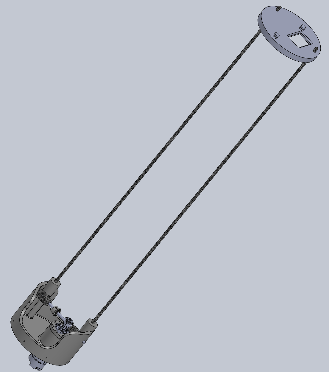
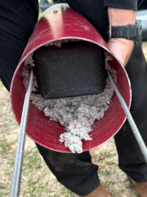
Shown above is a 3D render of the Separation Mechanism (left), and the mechanism inside the vehicle (right)