PCB Board
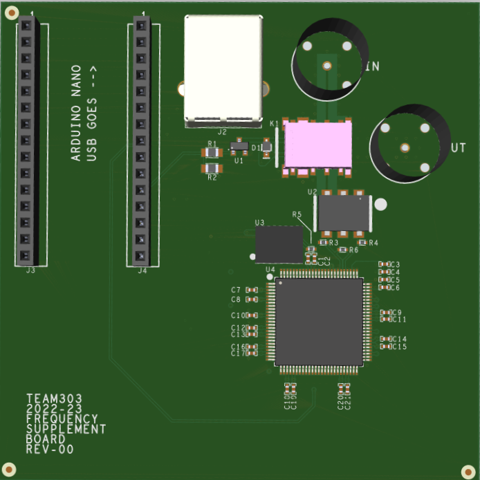
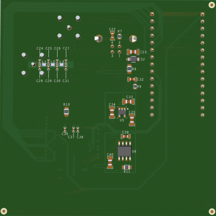
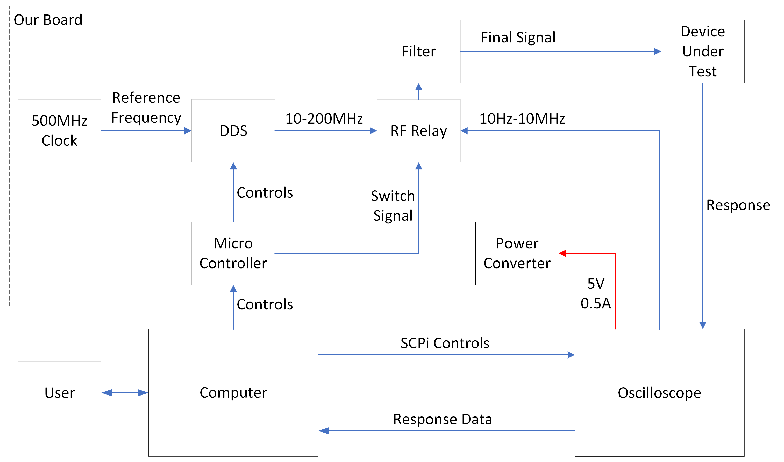
The hardware section of the programmable frequency multiplier consists of developing a printed circuit board (PCB) that will carry all the hardware components. The purpose of the PCB is to be controlled by the software from the computer to control the Oscilloscope to generate the desired frequency and control the response, along with the generation of a Bode Plot for the user. The PCB comprises four major components: A power converter, a microcontroller, a Direct Digital synthesizer (DDS), and an RF relay.
The power converter is the component in charge of turning on the PCB. The PCB will be connected from the Oscilloscope using a USB type B connector. From the USB, the power will go to two Low Dropout Regulators (LDOs), One converting the energy from 5V to 3.3V and Another from 3.3V to 1.8V.
The microcontroller selected is an onboard socketed Arduino nano that will control the DDS through control signals and serial lines (SPI). The Arduino will also control a relay that will select the desired output. There is also placement for potential filtering.
The DDS is the component in charge of the frequency generator. Controlled by the Arduino Nano and along a 400 MHz reference clock, the DDS can generate a single-tone sinewave output from 10 MHz to 200 MHz
The RF relay will serve as a bypass to the Oscilloscope controlled by the Arduino Nano. Since the Oscilloscope can generate signals from 0-20 MHz, if the user's desired frequency is within the range of 0 to 10 MHz, the RF relay will bypass the signal back to the Oscilloscope, stopping any signal coming from the DDS. However, if the desired frequency is between 10MHz to 200MHz, the RF relay will block the signal from the Oscilloscope and send the DDS-generated signal.
Oscilloscope
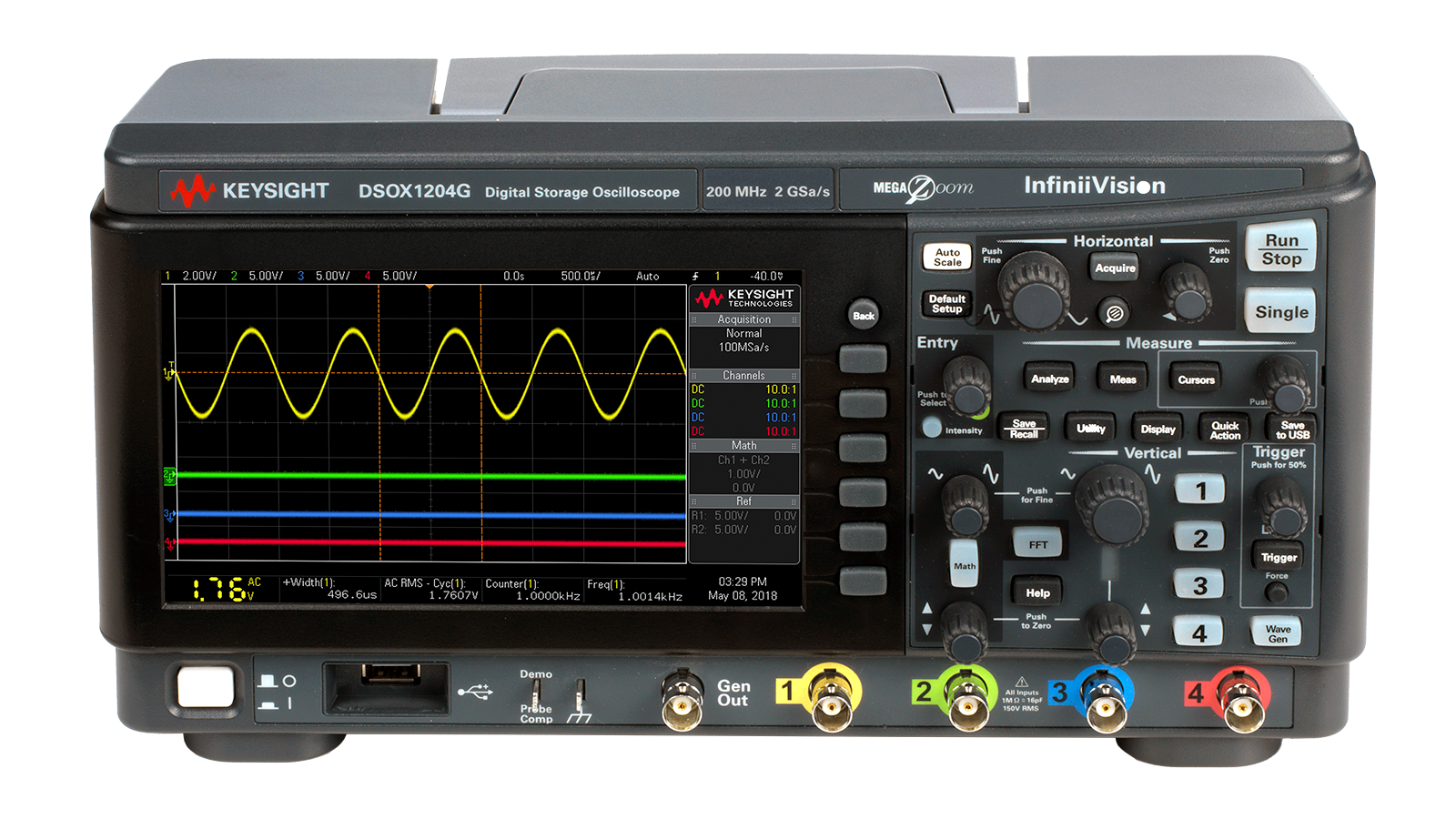
The oscilloscope used in our project is the Keysight DSOX1204G. In order to communicate with the computer and the PCB, a USB connection must be used for both. After connecting, the oscilloscope will be providing power to the PCB as well as frequencies ranging from 0 to 20MHz. Though the DSOX1204G is capable of reading signals from 0 to 200MHz, due to the 20MHz limitation of the on board function generator, our PCB and software was designed to supplement the remaining frequency range.
Computer
The software portion of our project consists of two major functions: to communicate with the PCB and oscilloscope through python commands and to support a website capable of displaying basic info and a bode plot. The goal of the software is to provide a simple and effective design that mitigates the work needed to be done by the user. The software should be capable of producing an appealing bode plot that can be tailored to the needs of the user without hassle.
In order to achieve these goals, the software will use SCPI and SPI commands to send and recieve data from the oscilloscope and PCB respectively. All exiting data will be recieved in the form of a .csv file which will then be processed by the website code to generate a bode plot for the user.