Meet Our Team


Team Leader:
Ricney Pasterin
Hardware Designer:
Alejandro Rodriguez
Software Designer:
Nicholas Talyanker
Secondary Designer:
Zachary Fogleman
Our Sponsors

Dr. Douglas M. Baney
Corporate Director of Education
Keysight Technologies

Antony Kahumbu
Product Management
Keysight Technologies

Dr. Fang Z. Peng
Professor of Engineering
FSU FAMU College of Engineering
Abstract
Frequency is defined as the number of times an event occurs within a set time. In electrical engineering, there are many techniques and tools to measure the frequencies of signals. Oscilloscopes are considered one of the most helpful tools for signal measurement. Newer models of oscilloscopes are capable of making, and then testing, their own signals. However, the cost to include parts that can produce higher frequency signals for such testing is high. For that reason, our project was proposed to provide a cheaper solution to making such signals, serving as a supportive tool for use with Keysight Technology's oscilloscopes. Our device creates signals at these expensive higher frequencies, allowing the oscilloscope to do more tests than it can alone. Our tool is designed for individuals and organizations looking for cheaper tools to create clean, low to high frequency signals to test other devices.
The project has a hardware and software aspect. The hardware portion is a Printed Circuit Board (PCB) that creates the frequency signal. The PCB includes a small computer to control the board and a Direct Digital Synthesis chip, which is the part that creates the frequency signals. The software portion is a program that talks to the PCB and the oscilloscope. The program provides the necessary controls and commands to create many different signals that are useful in testing. The program tells the board and oscilloscope to create the selected testing signals and to then measure the results of those tests. The program shows the results of the tests to the user as images. This program is also available to users through a website interface. This project provides an easy to use and affordable tool for studying, creating, and testing signals at higher frequencies.
Bode Plotting
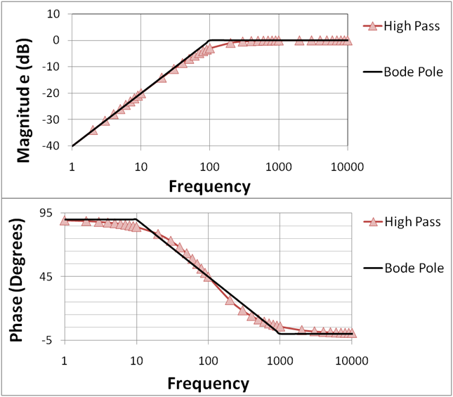
Bode plots are used to display the frequency response of a signal. This is done in a combinational plot showing the magnitude and phase change as a function of frequency. These plots are an essential tool for engineers to characterize a signal.
For the Programmable Frequency Multiplier, a bode plot is the prefered method of demonstrating the effectiveness of the system. Though the provided DSOX1204G has built in bode plotting functionality, it is not sufficient enough for the scope of the project. Attached to this site is a fully functional bode plot that works specifically with the provided oscilliscope and developed PCB board.
Future Work
- Create a casing around the developed Printed Circuit Board
- Use side attached BNC connectors for ease of access to the user
- Further development of Bode Plotting
- Capability to save image of Oscilloscope panel to speficied file
- Potential change in Microcontroller to streamline development
- Further testing to determine viability of PCB variants
- More powerful oscilloscope to measure waveform from the DDS
- Offline executable for Bode Plotting when internet is not available
- Printed Circuit Board design that does not rely on the Oscilloscope